Lets begin this , most people thinks TDA7293 is inferior chip to LM3886 due to dreadful reference circuit in datasheet.
Situation in TDA land is actually different, Jazz/Rock lover liked the chip for better HF response and sweeter midrange but Pop/EDM/Bass music people hated this chip for inferior bass response in comparison to LM3886.
LM3886 got inferior HF due to most horrible layout and lack of zobel in most mass market board.
In fact both chips are very close each other in performance, it all boils down to preference aka mosfet vs Bipolar (pick your poison).
This led to great war between LM3886 & TDA7293/94 users in forum.
I tested this circuit ±30v(maximum of my lab supply), at 29db gain, chip seems to be stable , I want to see if at ±35v if it oscillate.
This modification uses T Shaped feedback:
Theoretical advantages of T Shaped Feedback is well documented but i noticed a better sound quality.
Special Thanks to @danielwritesbac for extensive work on NFB and gain optimization,
Here, https://www.diyaudio.com/forums/chip-amps/226437-optimizing-tda7294-output-3.html#post3300269
Please Consult Datasheet first, My Drawing can be confusing,
https://www.st.com/resource/en/datasheet/tda7293.pdf
In Feedback , Either choose R1=R2 = 33k and R3 = 1.5K or R1=R2 = 22k and R3 = 1.2K.

Full Image: IMG-20200915-233005 — ImgBB
Doted Portion in Circuit is not tested.
Disclaimer: No TDA7293 is harmed in this experiment(as of today).
Situation in TDA land is actually different, Jazz/Rock lover liked the chip for better HF response and sweeter midrange but Pop/EDM/Bass music people hated this chip for inferior bass response in comparison to LM3886.
LM3886 got inferior HF due to most horrible layout and lack of zobel in most mass market board.
In fact both chips are very close each other in performance, it all boils down to preference aka mosfet vs Bipolar (pick your poison).
This led to great war between LM3886 & TDA7293/94 users in forum.
I tested this circuit ±30v(maximum of my lab supply), at 29db gain, chip seems to be stable , I want to see if at ±35v if it oscillate.
This modification uses T Shaped feedback:
Theoretical advantages of T Shaped Feedback is well documented but i noticed a better sound quality.
Special Thanks to @danielwritesbac for extensive work on NFB and gain optimization,
Here, https://www.diyaudio.com/forums/chip-amps/226437-optimizing-tda7294-output-3.html#post3300269
Please Consult Datasheet first, My Drawing can be confusing,
https://www.st.com/resource/en/datasheet/tda7293.pdf
In Feedback , Either choose R1=R2 = 33k and R3 = 1.5K or R1=R2 = 22k and R3 = 1.2K.
Full Image: IMG-20200915-233005 — ImgBB
Doted Portion in Circuit is not tested.
Disclaimer: No TDA7293 is harmed in this experiment(as of today).
Last edited:
Hi Dibya...do you think this T-shaped FB scheme can be implemented on one of your Xmas amp boards after stripping out all the servo components?
Thanks,
Pete
Thanks,
Pete
I’m thinking...on the Xmas board remove R1, Xmas board R19= new R2, Xmas board D9 = new R3 and Xmas board R16 = new R1. Jumper R15 on the Xmas board.
Signal paths are getting long, I know
Signal paths are getting long, I know
Hi Turion,
I think you can keep the servo circuit (and all it’s advantages) plus make the following changes to implement the “T” feedback like this:

Cut trace from node of R3/R1 to pin 2. Replace with new carbon film 20k resistor as shown. Do usual change of R15 to 10k to 47k. Change input cap C1 to 4.7uF film.
Alternatively, cut feedback R15 at old R3/R1 node and add jumper to bring directly to pin 2.
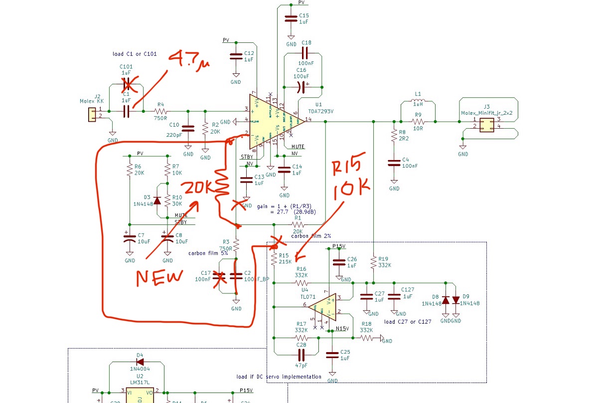
I think you can keep the servo circuit (and all it’s advantages) plus make the following changes to implement the “T” feedback like this:
Cut trace from node of R3/R1 to pin 2. Replace with new carbon film 20k resistor as shown. Do usual change of R15 to 10k to 47k. Change input cap C1 to 4.7uF film.
Alternatively, cut feedback R15 at old R3/R1 node and add jumper to bring directly to pin 2.
Attachments
Last edited:
Looks like I only have to add the new 20K to my one set since R15=10K was already in place as was C1-4.7uF.
Now just to figure out how to get the new resistor in place..hmm
Thanks X!
Now just to figure out how to get the new resistor in place..hmm
Thanks X!
Hi X..did you just change the picture?
Yes, first one was an error and did not see error until I posted. Then deleted it. These later ones are good I think.
Looks like I only have to add the new 20K to my one set since R15=10K was already in place as was C1-4.7uF.
Now just to figure out how to get the new resistor in place..hmm
Thanks X!
You might consider cutting the trace and scraping off solder mask and adding a tiny 0805 SMT resistor in the scraped off pads. Very compact mod that way.
You might consider cutting the trace and scraping off solder mask and adding a tiny 0805 SMT resistor in the scraped off pads. Very compact mod that way.
X:
Practicing the trace exposure/cut between R1 & Pin 2 I think my best shot would be mounting the new 20K resistor underneath the board and attaching its leads directly to the lead of R1 (toward the top of the board) to Pin 2 after I cut the PCB lead on the top of the board. I don’t think I can get a good isolated exposure of the track to solder on a 0805 (realistically a 0603 or a 0402 might fit better within the track).
I’m a little confused over the second thought of cutting the R15 node at R3/R1 and using a jumper to Pin 2 since the addition of the new 20K resistor (under the board) will join R15+3+1 to Pin 2 already. Just a better electronic way of bringing in the servo?
Thanks,
Pete
I gave the alternate way of connecting the servo straight to pin 2 as way to make sure the servo acts directly on pin 2, versus having to push it through the 20k. Although if we think of the 20k and 10k adding up to 30k, which is still less than 47k it might still work. I am not sure - you will just need to try it I guess.
One word of caution. I have no idea if this will work so do this at your own risk. It might oscillate?
One word of caution. I have no idea if this will work so do this at your own risk. It might oscillate?
xrk971;6575754One word of caution. I have no idea if this will work so do this at your own risk. It might oscillate?[/QUOTE said:Thanks X, Happy St Patty’s Day.....
Yeah, I understand the possible risk of doing experiments like this w/o a scope. I’ll have my light bulb tester & a fire extinguisher handy. 😉
I’m building one set w/o any servo components just to see what DC Offset looks like. I’ll try the T-FB Dibya mentioned in this sub-forum just to see if a) it works w/o disaster and b) if sound is any better.
I’ll try the T-FB on the top of the servo after that.
I always will keep my one stable Xmas amp build as is.
Regards
Pete
Its Highly experimental , I personally didnt hear any difference so left it.
Thanks Dibya....I guess we call it an "L" shaped feedback then?😉
Pete
Thanks Dibya....I guess we call it an "L" shaped feedback then?😉
Pete
Sounds Political to me 😛
Dibya and X: Does R1 = R2 set the input bias current? If the T (or L ;>)) feedback loop were engaged, and another 20K were added after R1 and before Pin 2, would R2 have to be increased to 40K, both in cases where the servo is kept intact or if the servo components are removed?
Thanks,
Pete
Thanks,
Pete
I had read somewhere, that for the TDA7293, if you separate the power supplies of the final stage and the driver, it improved the sound (pin 7, 13 and pin 8,15), and it was made with a particular diode. can someone give me some information about it?
Good day to everyone
I don't like at all bootstrap capacitors!
Has anyone measured the current requirements of the input stage (pin 7 and 8)? I have read in other threads regarding the TDA7293/4 that the best audio results are achieved when we supply the input stage with +38.5V -0- -38.5V and the output stage with +31V -0- -31V in order to get rid of the bootstrap capacitor (which I don't like at all)
Elias
@Elias Zacharopoulos,
I did measure that long time ago but don't remember the exact value, but it was low enough to not cause any problems, just a few mA. IIRC, I used a few additional windings on a toroid and an addditional diode bridge and reservoir caps to get the extra voltages and I also used cap multipliers to smooth out the input stage supply. The smoothness of the negative supply is really important because that's effectively the chip's reference voltage.
Catch diodes (Schottky type) are really recommended to connect from the output stage supply to the input stage supply pins to prevent the output stage supply ever becoming larger than the input supply (eg during startup) which kills the chip instantly. See TDA7294 datasheet section "Figure 20. High efficiency application circuit".

- Home
- Amplifiers
- Chip Amps
- TDA7293:Input & Output Optimization with T Shaped Feedback