Hi,
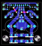
I'm laying out a small pcb for a tda2616 (I know Velleman makes a kit for it, but I don't like it) and I stumbled upon a quite basic question... what am I to do with the mute input (pin2) ? I've had a look on multiple schematics and some tie it to ground, some let it floating. A bit confusing.
The datasheet isn't very clear to me but maybe is it just me : TDA2616Q Datasheet pdf - 2 x 12 W hi-fi audio power amplifiers with mute - Philips
Thanks for any help on this.
I'm laying out a small pcb for a tda2616 (I know Velleman makes a kit for it, but I don't like it) and I stumbled upon a quite basic question... what am I to do with the mute input (pin2) ? I've had a look on multiple schematics and some tie it to ground, some let it floating. A bit confusing.
The datasheet isn't very clear to me but maybe is it just me
: TDA2616Q Datasheet pdf - 2 x 12 W hi-fi audio power amplifiers with mute - PhilipsThanks for any help on this.
Attachments
Simply do not connect the Mute pin. Floating works, connecting it to V+ via a 10 kOhm resistor also is OK. When drawn "low" the chip will mute. Can be a nice solution if you leave the amp powered on, using the mute pin will disconnect inputs so less noise and/or unwanted sounds (when not used). You can see it as a kind of standby function then. Power consumption won't change however.
BTW block diagram on page 3 of the data sheet is wrong. The switch in the middle of course switches both channels to mute ! Should be a double switch in the drawing.
BTW block diagram on page 3 of the data sheet is wrong. The switch in the middle of course switches both channels to mute ! Should be a double switch in the drawing.
Last edited:
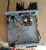
Here's the finished unit. Fairly basic, powered by an old printer's wallwart (2*10VAC/40VA).
Paired with some speakers coming from a broken Denon mini-system, it sounds pretty decent as an office system.
Paired with some speakers coming from a broken Denon mini-system, it sounds pretty decent as an office system.
Attachments

- Status
- Not open for further replies.