I am making a stereo amplifier using tda2030a in bridge mode(using 4 tda2030a ) and I want to gain 34w+34w =68w output approx.Please suggest me power supply layout for this. I am having 12-0-12 ---5amp transformer. Will it be sufficient or not. Also tell me whether regulation be needed in power supply or not.
Thanks in advance
Pls excuse my bad english🙂
Thanks in advance
Pls excuse my bad english🙂
Attachments
12V rectified will give you approximately 16Vdc lightly loaded.
This is well away from the +/- 22V maximum for the TDA2030.
Regulation will get a cleaner supply but limit your maximum power to less than what you would get without it.
You probably won't get your 34W + 34W because of the limits of your power supply.
Probably more like 20W + 20W.
Power supply ripple rejection is only 54dB. But you are using a bridge configuration.
I would say build it without regulation and test it to see if there are issues.
Let us know what the results are.
😕 I have also made this circuit but after few days both ICs burned out. Do you know what the reason is for that? 😕
I am making a stereo amplifier using tda2030a in bridge mode(using 4 tda2030a ) and I want to gain 34w+34w =68w output approx.Please suggest me power supply layout for this. I am having 12-0-12 ---5amp transformer. Will it be sufficient or not. Also tell me whether regulation be needed in power supply or not.
Thanks in advance
Pls excuse my bad english🙂
Hi,
Can I give you some advice, just know this series chip (internal).
"A" series has some pretty good performances, such as 150Khz power band, but suffer from a defect in the project. we call them "tweeter destructor" becouse,when switching in current protection, the final stage emits sine wave of maximum amplitude, at a frequency of 220-270Khz. just a time for destruct the TW,before destroy the chip. 🙂 can be measured well this strange behavior.
you can, however, make good use of this chip as a driver very simply. classical scheme with complementary Bjt, which you can find on Google.
regards
Last edited:
Hi,
Can I give you some advice, just know this series chip (internal).
"A" series has some pretty good performances, such as 150Khz power band, but suffer from a defect in the project. we call them "tweeter destructor" becouse,when switching in current protection, the final stage emits sine wave of maximum amplitude, at a frequency of 220-270Khz. just a time for destruct the TW,before destroy the chip. 🙂 can be measured well this strange behavior.
you can, however, make good use of this chip as a driver very simply. classical scheme with complementary Bjt, which you can find on Google.
regards
😕I have no idea what you are saying about.😕 😀Can you provide sample schematic for protect my bridged amplifier.😀
The 2030 is not feasible to use as a bridge amp in this way. Assuming you had the +/- 20V supplies. that would allow about a 35V peak voltage swing. The part does not have enough available current drive to do that into a typical 4 Ohm speaker or even an 8 Ohm speaker.I am making a stereo amplifier using tda2030a in bridge mode(using 4 tda2030a ) and I want to gain 34w+34w =68w output approx.Please suggest me power supply layout for this. I am having 12-0-12 ---5amp transformer. Will it be sufficient or not. Also tell me whether regulation be needed in power supply or not.
Thanks in advance
Pls excuse my bad english🙂
Hi,
Can I give you some advice, just know this series chip (internal).
"A" series has some pretty good performances, such as 150Khz power band, but suffer from a defect in the project. we call them "tweeter destructor" becouse,when switching in current protection, the final stage emits sine wave of maximum amplitude, at a frequency of 220-270Khz. just a time for destruct the TW,before destroy the chip. 🙂 can be measured well this strange behavior.
...
Is that the current-limiters oscillating due to the way the negative stage is driven? Or will it happen with any bridged 2030?
😕 I have also made this circuit but after few days both ICs burned out. Do you know what the reason is for that? 😕
Short answer: No
Longer answer: There must be a cause that could be found if all of the circumstances of your build and use was know...we need more details.
I have built this circuit . Using it with a pair of book shelf speakers 8ohms. 18-0-18 3 amp transformer. I had got the PCB ready made locally , paid about $0.30 for both channels(pcb only parts I had) . I recently replaced the tda2030a with tda2050. It sounds much warmer(and nicer) with the tda2050.
- Status
- Not open for further replies.
- Home
- Amplifiers
- Power Supplies
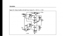
- TDA2030A Power Supply bridge mode