Dear Members,
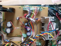
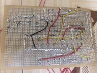
I built a new TDA2009A Hi-Fi audio amplifier for 5.1 surround system. I prepared three TDA2009A PCB boards for driving 6 speakers. Each board is supplied by individual power supply made of 30V step-down transformer, KBP206G bridge rectifier, 2nos. of 2200MicroF capacitors in parallel, L7824CT 24V positive voltage regulator. And also attaching schematic diagram for your reference and this is different from PCB layout shown in TDA2009A datasheet. Now the problem is that sometimes i am getting output from single channel and most of the time I am not getting output from amplifier boards. Please look into the schematic and provide your suggestions and i spent lot of time to debug the circuit but in vain not able to get the sound from amplifier boards.
Thanks.
Bhaskar
L7824CT 24V positive voltage regulator. And also
I prepared three TDA2009A PCB boards for driving 6 speakers.
Dear Members,
I built a new TDA2009A Hi-Fi audio amplifier for 5.1 surround system. I prepared three TDA2009A PCB boards for driving 6 speakers. Each board is supplied by individual power supply made of 30V step-down transformer, KBP206G bridge rectifier, 2nos. of 2200MicroF capacitors in parallel, L7824CT 24V positive voltage regulator. And also attaching schematic diagram for your reference and this is different from PCB layout shown in TDA2009A datasheet. Now the problem is that sometimes i am getting output from single channel and most of the time I am not getting output from amplifier boards. Please look into the schematic and provide your suggestions and i spent lot of time to debug the circuit but in vain not able to get the sound from amplifier boards. Also note that complete circuit is made by me due to this circuit is not functioning properly.
Thanks.
Bhaskar
Dear Members,
Dear Members,
I built a new TDA2009A Hi-Fi audio amplifier for 5.1 surround system. I prepared three TDA2009A PCB boards for driving 6 speakers. Each board is supplied by individual power supply made of 30V step-down transformer, KBP206G bridge rectifier, 2nos. of 2200MicroF capacitors in parallel, L7824CT 24V positive voltage regulator. And also attaching schematic diagram for your reference and this is different from PCB layout shown in TDA2009A datasheet. Now the problem is that sometimes i am getting output from single channel and most of the time I am not getting output from amplifier boards. Please look into the schematic and provide your suggestions and i spent lot of time to debug the circuit but in vain not able to get the sound from amplifier boards. Also note that complete circuit is made by me due to this circuit is not functioning properly.
Thanks.
Bhaskar
Dear Members,
I built a new TDA2009A Hi-Fi audio amplifier for 5.1 surround system. I prepared three TDA2009A PCB boards for driving 6 speakers. Each board is supplied by individual power supply made of 30V step-down transformer, KBP206G bridge rectifier, 2nos. of 2200MicroF capacitors in parallel, L7824CT 24V positive voltage regulator. And also attaching schematic diagram for your reference and this is different from PCB layout shown in TDA2009A datasheet. Now the problem is that sometimes i am getting output from single channel and most of the time I am not getting output from amplifier boards. Please look into the schematic and provide your suggestions and i spent lot of time to debug the circuit but in vain not able to get the sound from amplifier boards. Also note that complete circuit is made by me due to this circuit is not functioning properly.
Thanks.
Bhaskar
Attachments
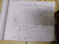

Download the datasheet for the IC and look at the application circuit. The chip will not function properly if you don't follow the manufacturers suggested circuit. For one thing, you left the inverting inputs open (pins 2 and 4).
Lay the board out so the external components are close to the chip as possible and the return grounds for the input and negative feedback don't have power currents flowing in them (research star grounding).
Finally, build one prototype circuit and test for proper operation before building the entire amp.
- Status
- Not open for further replies.