Hey guys,
I got a Taramps HD8K 1-ohm in (R5 PCB), rebuilt the power supply and amplifier powered up ok, good r-r oscillation (didn't have to mess with the output section). Inserted audio and passes clean audio. noticed it had around 5.32vdc on the speaker terminals. I adjusted the offset potentiometer and got it to around 400mv.
When connected to a speaker I noticed it sucks in the speaker and slowly releases it. measuring the DC on the speaker terminals, it goes to -3.15vdc and quickly settles to around 400mv.
I've fiddled with the offset pot, 400mv is the lowest I could get it. So far all diodes and resistors checked ok in circuit in the output section. Are there any solutions to the spk terminal DC or suggestions what to look into?
Are the two regulators very nearly the same magnitude in voltage?
Are the resistors between the regulators and the DC pot within tolerance?
Are the resistors between the regulators and the DC pot within tolerance?
On point a usual Perry,
the two regulators (7812) in the output section:
REG3: pin 1: 25.04vdc
pin 3: 15.09vdc
REG4: pin 1:25.10vdc
pin3: 12.03vdc
the two regulators (7812) in the output section:
REG3: pin 1: 25.04vdc
pin 3: 15.09vdc
REG4: pin 1:25.10vdc
pin3: 12.03vdc
I'm back at this again:
I've replaced both regulators, powered up and both read 11.92v and 11.89vdc, pin 3.
I've adjusted the offset potentiometer to around -540mv, the best I could get it as its very sensitive (this was without a load connected). cycled power and it powered up with an initial -2.48vdc and settled down to around -500mv.
I then tried it with a subwoofer, with meter leads connected, it did the same, with an initial sucking in of the woofer and settling to around -500mv.
I've checked the associated opamp which checked ok CI4 (TL072) and replaced it as a precaution with similar results.
I did some checks in the audio side leading into pins 2 and 3 of CI6 and CI7 (TL712), I found one opamp with 1v of dc and replaced this also with similar results.
I forgot to mention, since being rebuilt the amplifier once powered has the power LED solid and the prot LED lit low/dim.
looking at the gate drives, I got a somewhat irregular waveform on both lowsides FETs G-S, I checked through the drive components in circuit and they tested ok, both IR2010S have clean square waves entering. I replaced both drivers and this remedied only one low side gate drive the other remained the same.
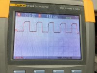
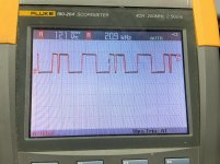
I've attached a pic of the suspicious waveform, the scope is reading this as roughly half the freq (22.2khz) of the other sides of the bridge (41.8khz). The drivers are new Mouser units and I used as minimal heat as possible.
Would this warrant another replacement driver? or another of the drive components?
I've replaced both regulators, powered up and both read 11.92v and 11.89vdc, pin 3.
I've adjusted the offset potentiometer to around -540mv, the best I could get it as its very sensitive (this was without a load connected). cycled power and it powered up with an initial -2.48vdc and settled down to around -500mv.
I then tried it with a subwoofer, with meter leads connected, it did the same, with an initial sucking in of the woofer and settling to around -500mv.
I've checked the associated opamp which checked ok CI4 (TL072) and replaced it as a precaution with similar results.
I did some checks in the audio side leading into pins 2 and 3 of CI6 and CI7 (TL712), I found one opamp with 1v of dc and replaced this also with similar results.
I forgot to mention, since being rebuilt the amplifier once powered has the power LED solid and the prot LED lit low/dim.
looking at the gate drives, I got a somewhat irregular waveform on both lowsides FETs G-S, I checked through the drive components in circuit and they tested ok, both IR2010S have clean square waves entering. I replaced both drivers and this remedied only one low side gate drive the other remained the same.
I've attached a pic of the suspicious waveform, the scope is reading this as roughly half the freq (22.2khz) of the other sides of the bridge (41.8khz). The drivers are new Mouser units and I used as minimal heat as possible.
Would this warrant another replacement driver? or another of the drive components?
Attachments

In my experience with these amps when you get the power led and the clip or protection light lit but dim and the strange issues with the speaker sucking in at power up .
Most likely the driver ic’s in the audio section are bad
I’ve fixed 3 amps and all the same issue in these with the driver ic’s in the audio section being bad even tho all outputs are fine and the amp works just not correctly
Most likely the driver ic’s in the audio section are bad
I’ve fixed 3 amps and all the same issue in these with the driver ic’s in the audio section being bad even tho all outputs are fine and the amp works just not correctly
What is the DC voltage on all 3 terminals of the DC offset pot fully clockwise?
And the center terminal fully counter-clockwise?
And the center terminal fully counter-clockwise?
Offset pot, pins 1 to 3:
CW> 1.34v 284mv 283mv
CCW> 335mv 335mv 1.25v
I replaced only the driver for the half bridge with the "lower" oscillating freq, but no change.
CW> 1.34v 284mv 283mv
CCW> 335mv 335mv 1.25v
I replaced only the driver for the half bridge with the "lower" oscillating freq, but no change.
Set the pot to get the lowest offset and post the DC voltage on all terminals of C14 and C15. Copy and paste and fill in the blanks.
Pin 1:
Pin 2:
Pin 3:
Pin 4:
Pin 5:
Pin 6:
Pin 7:
Pin 8:
Pin 1:
Pin 2:
Pin 3:
Pin 4:
Pin 5:
Pin 6:
Pin 7:
Pin 8:
offset: 512mv
C14
Pin 1: -0.014
Pin 2: -0.002
Pin 3: 0.001
Pin 4: -14.78
Pin 5: 0.001
Pin 6: 0.004
Pin 7: 0.003
Pin 8: 14.77
c15
Pin 1: 0.008
Pin 2: 0.005
Pin 3: 0.004
Pin 4: -14.78
Pin 5: 0.004
Pin 6: 0.007
Pin 7: 0.007
Pin 8: 14,77
C14
Pin 1: -0.014
Pin 2: -0.002
Pin 3: 0.001
Pin 4: -14.78
Pin 5: 0.001
Pin 6: 0.004
Pin 7: 0.003
Pin 8: 14.77
c15
Pin 1: 0.008
Pin 2: 0.005
Pin 3: 0.004
Pin 4: -14.78
Pin 5: 0.004
Pin 6: 0.007
Pin 7: 0.007
Pin 8: 14,77

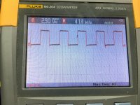
I pulled both FETs : FET2 and FET19 (IRFP4768), and checked out of circuit, both tested ok, installed one at a time and amplifier produces a clean gate drive now with correct 41khz oscillation. I swapped around the FETs to confirm this one is defective and it confirmed it.
The offset now settles around 100mv, however I still have the -3v turn on thump which quickly settles and the protect LED is lit dim.
The offset now settles around 100mv, however I still have the -3v turn on thump which quickly settles and the protect LED is lit dim.
So, the only problem was one FET?
Did that FET show any leakage from the gate to the other terminals (meter on ohms)?
Did that FET show any leakage from the gate to the other terminals (meter on ohms)?
- Home
- General Interest
- Car Audio
- Taramps HD8000 DC offset