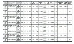
I have the chance to pick up some sub drivers from these listed in the attached spec sheet. I have been considering building some Tapped horns to cover upto 100Hz in my front horn based active system.
I have looked at the Lab12 TH in the past but had concluded it was too big for the space i have in my corners, so was wondering if using a 10" driver allow a cabinet that acceptable.
The horn can have a line upto 4 m long and a mouth of around 800cm2 max.
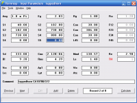
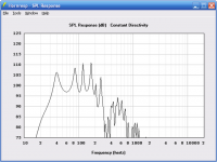
I have tried simulating with Hornresp without any success an expanding and contracting line, not being able to get a flat response that goes below 35 Hz. What am i doing wrong or is it that a driver with stiff suspension (low VAS) isn't suitable?
See attached one of my poor attempts.
I am also not sure if the spec sheet values are 100% accurate as when i determine values for mmd for example on different coil configurations i get opposing trends form the publised data.
I have looked at the Lab12 TH in the past but had concluded it was too big for the space i have in my corners, so was wondering if using a 10" driver allow a cabinet that acceptable.
The horn can have a line upto 4 m long and a mouth of around 800cm2 max.
I have tried simulating with Hornresp without any success an expanding and contracting line, not being able to get a flat response that goes below 35 Hz. What am i doing wrong or is it that a driver with stiff suspension (low VAS) isn't suitable?
See attached one of my poor attempts.
I am also not sure if the spec sheet values are 100% accurate as when i determine values for mmd for example on different coil configurations i get opposing trends form the publised data.
Attachments
The problem isn't the low VAS, it's the low BL (and relatively high mass). It's going to be peaky.
I had simmed using the 2/2 coils not the 4/4 coils, so 9.2 not 13.5.
There are some double magnet versions which have a higher BL, but a slightly higher mass also, which i have tried simming also. With the CA10900/4/4 i got a similarly poor response. The cone mass and BL of this driver are in the same sort of ballpark as the LAB12, so am a little confused why it sims so bad.
There are some double magnet versions which have a higher BL, but a slightly higher mass also, which i have tried simming also. With the CA10900/4/4 i got a similarly poor response. The cone mass and BL of this driver are in the same sort of ballpark as the LAB12, so am a little confused why it sims so bad.
Attachments
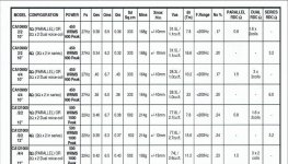
caculating the specs using horn resp, using vas, fs, qts, qes, qms of the 2nd driver in the first pic you posted (2/2) results in a calculated bl of 13.87.
with this bl, it is possible to make a good flh, and a decent th (they are about the same size), with response down to 40hz.
with this bl, it is possible to make a good flh, and a decent th (they are about the same size), with response down to 40hz.
Thanks for those two simulations. This gives a good foundation to tweek the design from. The TQWT is significantly smaller than the TH but at not as efficient, is this the only thing being sacrificed by going for the TQWT over the TH?
Thanks for those two simulations. This gives a good foundation to tweek the design from. The TQWT is significantly smaller than the TH but at not as efficient, is this the only thing being sacrificed by going for the TQWT over the TH?
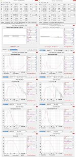
I have been further tweeking myself and have come up with the following. Needed to slug the driver with a bit of resistance and add a inductor in series to achieve this response. How flat is needed? I can get it flatter but sacrifice the top end, i need to get to around 90 Hz to integrate with my midbass horn. I assume some strategically placed bits of foam can tame the HF somewhat(?).
I simmed the 4 x4 coil option as well which has a bigger BL and a slightly lighter cone, but have not with a similar level of tweeking achieved a similarly flat response, ( plots on right) Thos confuses me as i through it would be easier as the cone is more controlled.
I know some put a Karlson mouth on TL to smooth the response, has anyone done a similar thing with a TH? ( Then is a TH a Karlson resonator?)
Attachments
1. Try to get the response you want without adding Le and Re.
2. Use PAR segments, not CON.
3. Use 2 pi unless you plan to load the sub in a corner.
4. Try not to change flare rate at the driver tap points unless you have a significant reason to do so and are already planning for it in the folding stage.
5. Narrow peaks like the ones from 100 hz and up in your sims will be largely damped by the enclosure losses. But still a 15 db peak isn't going to disappear. If you want a really flat response a small horn isn't the best choice.
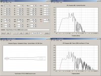
Here's an example, no Le or Re added, no flare rate changes at either driver tap point (only at S3), and staying within your size limits from post 1 (4m length, 800 sq cm mouth), 120 liters. Light grey line is the tapped horn. Black line is a ported box with the same driver. 40 liters. Both shown at 10 mm (I didn't notice xmax was listed in the chart in post 1 and I'm not going to change it now). Your size limit doesn't allow for a whole lot of advantage over a much smaller ported box. The tapped horn will be louder of course, but I like to see a bit more advantage over a ported box before going to the cost and complexity of building a tapped horn. I wouldn't use this driver personally, not enough xmax.
2. Use PAR segments, not CON.
3. Use 2 pi unless you plan to load the sub in a corner.
4. Try not to change flare rate at the driver tap points unless you have a significant reason to do so and are already planning for it in the folding stage.
5. Narrow peaks like the ones from 100 hz and up in your sims will be largely damped by the enclosure losses. But still a 15 db peak isn't going to disappear. If you want a really flat response a small horn isn't the best choice.
Here's an example, no Le or Re added, no flare rate changes at either driver tap point (only at S3), and staying within your size limits from post 1 (4m length, 800 sq cm mouth), 120 liters. Light grey line is the tapped horn. Black line is a ported box with the same driver. 40 liters. Both shown at 10 mm (I didn't notice xmax was listed in the chart in post 1 and I'm not going to change it now). Your size limit doesn't allow for a whole lot of advantage over a much smaller ported box. The tapped horn will be louder of course, but I like to see a bit more advantage over a ported box before going to the cost and complexity of building a tapped horn. I wouldn't use this driver personally, not enough xmax.
An externally hosted image should be here but it was not working when we last tested it.
Again thanks for the input. I need to get a little more info on the drivers, allegedly the xmax is the linear portion of the travel. As some of you have probably guessed they are fabian acoustic sub drivers, which someone close to me has NOS, which he is off loading from an old business venture. I have the oppotunity to measure the drivers to get real T/S specs. Weighing these drivers up against the Lab12 v cabinet size is my dillemia. I am open to suggestions on a better 10" driver.
I am intending to place the cabinets in the corner of some alcoves, which is wasted space anyway. Before anyone suggests using the walls for the mouth of a FLH the width of shortest alcove wall is only 400mm.
As you suggest a ported box over the TH, this again raises the question which is difficult to answer, the benefits of the TH. I have chosen to pursue this approach as they seem to be the sub of choice for horn rigs, assuming others have quantified the benefits and concluded its the best solution
I don't suggest a ported box, but all your tapped horn designs should be compared to a ported box with the same driver to make sure the tapped horn is worth it's size.
IMO no driver with low xmax is suitable for a tapped horn. 8.5 mm is low xmax.
You could use 3 of those drivers in a ported box the same size as a single driver tapped horn, that should be considered. Tapped horns do have benefits but you have to choose the right driver and it has to be fairly large, otherwise a lot of the benefits disappear.
Looking at what other drivers we can get in the UK, i noticed that i can get 2 peerless xls10's for almost the price of a Lab12. I noticed this previous post using a pair in series. got to get my head around what a TH -Spud arrangement is, i assume the drivers are in push pull to minimise 2nd order distortion.
http://www.diyaudio.com/forums/subwoofers/181324-peerless-xls10.html#post2437126
http://www.diyaudio.com/forums/subwoofers/181324-peerless-xls10.html#post2437126
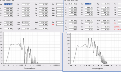
After reading up about spud TH's i have a couple of points to clarify. The Hornresp sim below for a pair a 10" peerless drivers in a "spud TH" arrangement seem to be wired in series. Other threads tend to suggest that the drivers are arranged in push pull (isobaric?) or is it that the drivers are wired in series but positioned facing opposite directions? The other point of clarification, is if in Hornresp the position of the driver is 20cm from the end, am i right to assume that i would position each driver equispaced each side of this point? The reason i ask is its going to be difficult getting a 10" driver 8" from the end.
Attachments
If you want the drivers to be like the SPUD, they are positioned one after the other (one closer to the beginning of the line than the other), one is flipped backwards so one will pull and one will push but they will be going in the same direction. They can be wired in series or parallel depending on what drivers are used and what final impedance you want. Use the midpoint between the drivers as S2.
If you are unclear what the SPUD looks like inside just do a quick image search. There are pictures of it all over the place, even the plans.
If you are unclear what the SPUD looks like inside just do a quick image search. There are pictures of it all over the place, even the plans.
- Status
- Not open for further replies.
- Home
- Loudspeakers
- Subwoofers
- Tapped Horn Sub Using Low VAS drivers