This is my first post on here, but I've been kicking this idea around for a while, on want to get some feedback.
I have a 2007 mazda 3 hatchback and desired a sub and amplifier placement that would still permit full use of the back loading aread. After looking at it, I decided I would build a large foot print, but thin box, that would replace the storage tray and cover in the bottom of the trunk (which conveniently is rectangular) and an amplifier under the passenger seat.
I came up with a design that would basically raise the floor of the trunk 4" but still leave plenty of space for throwing stuff in the back. I've always wanted to do a tapped horn design, and figured this would work for this as I could fold the horn path into the box, and have no drivers or speaker grills exposed to get damaged.
I also have a bunch of Dayton W5-704D drivers laying around that were bought on sale ($25 each) with the intent to build a 5.1 system, but they are no longer needed for that. These drivers are by no means designed for sub use, with there small size and xmax (3.3mm), but tapped horns are known for getting a surprising amount of performance out of small drivers. I'm not expecting earth shattering bass, but rather being able to play at above 90 db with good extension and clarity.
Here is what I came up with:
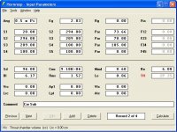
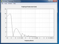
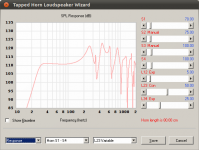
-The first attachment is the hornresp input parameters. It is approx a 50 liter box with 4 of the daytons. I would use two boxes in the trunk.

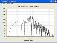
-The second is spl at 2.83 volts (one watt) in .5 pi space (which I heard is appropriate for cars) for one box. I'm hoping the roll off should be shallow enough that cabin gain should extend response flat to 20 Hz.

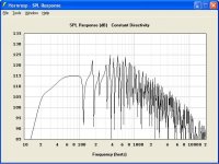
-The third is spl at 12 volts (around 40 watts) which is pretty much where the drivers will run out of excursion, and maybe overall 6db louder with the second box.

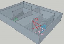
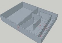
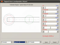
-Fourth is a sketchup of the folding. The end of the path in the bottom corner is where the opening will be, ending up in the corner of the trunk. The empty side will be a mirror of the close side. The circles represent the drivers. Also the driver closest to the end of the path is the location in the hornresp model. I also modeled the other three (as they move down the line) and think the combination should actually flatten and extend the passband.

Now I don't know if I should believe these little drivers can really reach 120 db at 60 Hz (thinking the cones can't handle the pressure) but if they get anywhere close, I'll be happy.
Thoughts?
I have a 2007 mazda 3 hatchback and desired a sub and amplifier placement that would still permit full use of the back loading aread. After looking at it, I decided I would build a large foot print, but thin box, that would replace the storage tray and cover in the bottom of the trunk (which conveniently is rectangular) and an amplifier under the passenger seat.
I came up with a design that would basically raise the floor of the trunk 4" but still leave plenty of space for throwing stuff in the back. I've always wanted to do a tapped horn design, and figured this would work for this as I could fold the horn path into the box, and have no drivers or speaker grills exposed to get damaged.
I also have a bunch of Dayton W5-704D drivers laying around that were bought on sale ($25 each) with the intent to build a 5.1 system, but they are no longer needed for that. These drivers are by no means designed for sub use, with there small size and xmax (3.3mm), but tapped horns are known for getting a surprising amount of performance out of small drivers. I'm not expecting earth shattering bass, but rather being able to play at above 90 db with good extension and clarity.
Here is what I came up with:
-The first attachment is the hornresp input parameters. It is approx a 50 liter box with 4 of the daytons. I would use two boxes in the trunk.
-The second is spl at 2.83 volts (one watt) in .5 pi space (which I heard is appropriate for cars) for one box. I'm hoping the roll off should be shallow enough that cabin gain should extend response flat to 20 Hz.
-The third is spl at 12 volts (around 40 watts) which is pretty much where the drivers will run out of excursion, and maybe overall 6db louder with the second box.
-Fourth is a sketchup of the folding. The end of the path in the bottom corner is where the opening will be, ending up in the corner of the trunk. The empty side will be a mirror of the close side. The circles represent the drivers. Also the driver closest to the end of the path is the location in the hornresp model. I also modeled the other three (as they move down the line) and think the combination should actually flatten and extend the passband.
Now I don't know if I should believe these little drivers can really reach 120 db at 60 Hz (thinking the cones can't handle the pressure) but if they get anywhere close, I'll be happy.
Thoughts?
Attachments

Last edited:
HI there r: Please post your Xmax curve from HR, the T/S parameters calculated by HR (requires a double click on Sd), the HR sketch of the path layout and show the exit port in the sketch, these will the diy community evaluate your design. The path does not seem to follow the input screen with reghard to a continuous path (you seem to have added a resonator attached to the final section where you stated the exit port will be located). regards, Michael
You'd be better off doing what I've done in subaru wrx... do a 'spare tire sub' but not a replace the spare tire sub, something different.
Flip your spare tire over, so you have an area that a 10" driver magnet can hang down into.
Build a square box that is only as high as original deck that covers the entire back area, making the top irregular shape to exactly fit the contours of the car.
"Rear Mount" the sub in the "sealed" box so the magnet hangs down less than front mounting, and then screw it together. (using dowel braces to keep the big top/bottom panels from flexing)
Back by the hatch latch, cut a small about 2"x10" notch in your top irregular shaped panel.
Cover in carpet.
Enjoy.
It is the biggest bass you can stealth in a car of your size.
Last edited:
Thank you for your responses.
For Michael:
xmax curve at 12 volts, where driver reaches 3.3mm xmax at 45 Hz

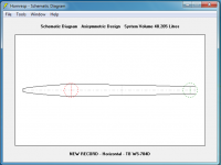
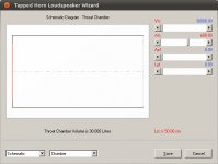
The Hornresp schematic:

Updated image of the box with S1, S2, S3, and S4 marked (with MS Paint 🙂) I think you were looking at the horn path backwards.

and Jbell, thank you for suggestion, that is an interesting idea, I'll keep it in mind. I've already had a sealed, a ported, and bandpass in various cars, and never been fully happy with any of them, and like I said I already have the drivers (I don't have a 10" on hand) which have no other purpose, and have been wanting to try a tapped horn. I've heard two different ones before, and loved them. Also according to modeling, this should match a typical 12" sealed in output with better low end and phase response. And to be honest, I like making things people haven't made before, and I like challenges. If I can take 8- 5 1/4" hifi midwoofers and make a good sub, it'll be much more satisfying. If it doesn't work, i've wasted $25 in wood and a day off.
thanks again for your responses!
Ryan
For Michael:
xmax curve at 12 volts, where driver reaches 3.3mm xmax at 45 Hz
The Hornresp schematic:
Updated image of the box with S1, S2, S3, and S4 marked (with MS Paint 🙂) I think you were looking at the horn path backwards.
and Jbell, thank you for suggestion, that is an interesting idea, I'll keep it in mind. I've already had a sealed, a ported, and bandpass in various cars, and never been fully happy with any of them, and like I said I already have the drivers (I don't have a 10" on hand) which have no other purpose, and have been wanting to try a tapped horn. I've heard two different ones before, and loved them. Also according to modeling, this should match a typical 12" sealed in output with better low end and phase response. And to be honest, I like making things people haven't made before, and I like challenges. If I can take 8- 5 1/4" hifi midwoofers and make a good sub, it'll be much more satisfying. If it doesn't work, i've wasted $25 in wood and a day off.
thanks again for your responses!
Ryan
Attachments
good luck ryan. please document and post your build, I'm interested.
My suggestion is a hybrid. It's not really sealed, not bandpass (although closest to bandpass) and not really front loaded horn. Although it has elements of each.
It's one of those "when the hatch is open the bass disappears" kinda designs. It really uses the floor and hatch shape as part of the system. That's why I think it works so well.
I also like it because I'm just a sucker for stealth...
Hi ryanroehl,
Nice workup, but the locations for S1-S5 are defined in Hornresp, and cannot be arbitrarily assigned otherwise. Also, if you add a second section between the driver(s) and the output opening (driver @ S3 - output @ S5) you need to click on the red TH, and change it into TH1; otherwise, in a 4-section TH the driver is located between S3 and S4.
Regards,
Attachments
Sorry I mislabeled my diagram. S1 and S2 are correct (with the modeled driver at S2), what is labeled as S4 should be S5 (the exit), and S3 should be S4 (the tap on the backside of the driver) and S3 should be at the 180 degree bend in the middle.
JBell, your idea is interesting. I modeled it up in hornresp, as it is basically a band pass horn, and there is some potential there. Maybe if this doesn't work I'll try that next...
JBell, your idea is interesting. I modeled it up in hornresp, as it is basically a band pass horn, and there is some potential there. Maybe if this doesn't work I'll try that next...
4x5.25 driver TH,car sub
Hi there R: Are you still modeling the origional TH, or have you started construction? This does not seem to be a dificult enclosure to construct. Hope you will continue to post construction photos/comments and listining evaluation, would be interested in how much cabin gain you actually obtained below 50hz. ...Michael
....JBell, your idea is interesting. I modeled it up in hornresp, as it is basically a band pass horn, and there is some potential there.
Maybe if this [origional proposal] doesn't work I'll try that next [J Bell's sugestion]
Hi there R: Are you still modeling the origional TH, or have you started construction? This does not seem to be a dificult enclosure to construct. Hope you will continue to post construction photos/comments and listining evaluation, would be interested in how much cabin gain you actually obtained below 50hz. ...Michael
The large area between S1 and S2 is primarily just acting as a chamber.
The line length doesn't look right for the response chart. are you sure you have all the number right?
What are the outside dimensions of this box?
Regards,
Eric
The line length doesn't look right for the response chart. are you sure you have all the number right?
What are the outside dimensions of this box?
Regards,
Eric
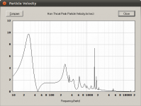
Looking at your box, and making some guesstimates, I see the following: (simulated at ~11V and 0.5pi space, or ~15W input for 4 drivers), extrapolated, this would be about 117dB capable with both box halves and all 8 drivers figured in down to ~30hz. I think this may be a bit optimistic, as I look back on it I suspect I have overestimated the box size a bit... the actual low frequency limit may be closer to ~35hz
Regards,
Eric
Regards,
Eric
Attachments

Last edited:
I would edit this in, but the forum doesn't allow it:
The problem I see with the design, is that it wastes a ton of displacement. Most of the driver displacement in the design you are proposing, is being fluttered away as more efficiency than is needed. If you want to use all 8 drivers, it would be better to reduce the sophistication level of the box design and use more electrical power. As it stands currently, the box design, IMO, is a waste of potential.
On a very general note; an "ideal" to "strive" for in box design, is such that both the thermal [Pe] and displacement [Xmax] capabilities of a driver are being utilised near their maximum. Your design is extraordinarily lopsided, leaving a ton of Pe on the table- - reaching xmax well before there is any electrical or thermal issue in a reasonable car sub application. Given the same box space, you can easily achieve the same or better output with less drivers. Or more output with some variation of box or driver combination 🙂
Regards,
Eric
Here's some good reading on this topic, from my friend mark....
http://www.diyaudio.com/forums/subwoofers/145603-tapped-horn-car.html
http://www.diyaudio.com/forums/subwoofers/145603-tapped-horn-car.html
Suggestion:
Sell or trade the TBs and get these instead: Tang Band W5-1138SM 5-1/4" Neodymium Subwoofer 264-831
Here's 8 of them charted at ~320W in ~90 litres worth of tapped TL...


------
You really only need 2 of them in about a 60 litre TH to match the performance of all 8 of those W5-704s in the current design. Regards,
Eric
Sell or trade the TBs and get these instead: Tang Band W5-1138SM 5-1/4" Neodymium Subwoofer 264-831
Here's 8 of them charted at ~320W in ~90 litres worth of tapped TL...
------
You really only need 2 of them in about a 60 litre TH to match the performance of all 8 of those W5-704s in the current design. Regards,
Eric
Sorry for the long break in response, but work has been hectic, and I've been working multiple 16 hour days in the last two weeks. Thanks for all the responses guys, it's pretty great to see them all. I have since left the tang band 5 1/4" on the wayside for now. I was looking at the modeled impulse response of the cabinet, and was not impressed. I was well aware that I was looking at a driver that was far from ideal, but I already had them and as long as I got good sound quality out of them, was willing to try. I think I will use them as mid basses upfront as I do have some 1" tweeters that will go well with them.
What I have done is use Jbell's idea of the cabinet with a driver mounted down firing with the magnet hanging in the middle of the spare tire well. I was playing around with it, modeling it as a very short front loaded band pass horn (with the box as the rear chamber, the tire well as the front chamber, the opening near the hatch as the throat, and the hatch shape as the flare) and saw potential. I had last weekend off so I went ahead and built it. I used an Eminence Lab 12 (one of the other drivers I had laying around) and ported the box to help fill in the low end. Initial impressions are good. It has a strong kick in the 60-80Hz range (letting me know the horn loading is working) with extension down to around 23 Hz (observed my simply sweeping a sine wave). If the horn loading was not working, and it simply was a ported box, it would be weighted with far more low end then it has now.
In the next couple of days I will post pics of the build and measurements of frequency response and efficiency.
I think a hatch car will yield higher peak numbers than .5pi. Isn't it close to30db gain for cabin gain!
Well cabin gain varies with frequency, mine starts at around 60-70 Hz and give you about a 9-10 db increase each octave down, with that increase reducing as you go lower (I dropped a studio sub into the car that is -3db at 18 hz and measured it real quick and rough like). I modeled it to be flat from 70 on up, and then fall off at about 9db an octave to around 25hz where it falls off. I also modeled it in .5 space because of all the close walls. I've never actually seen anyone give good comparison to hornresp .5 space vs an enclosed car...
I'll post the two graphs once I have time later.
I'll post the two graphs once I have time later.
I assume you ported into the cabin, and not into the wheel-well?
fun design, isn't it ??
For stealth in a small hatch, it's the best hybrid design I've come up with.
fun design, isn't it ??
For stealth in a small hatch, it's the best hybrid design I've come up with.
Last edited:
- Status
- Not open for further replies.
- Home
- Loudspeakers
- Subwoofers
- Tapped Horn Car Sub 5 1/4" woofers