Well, did the stealth mod and put the t-amp in another case. The only problem: nothing coming out. No music, no hiss, no squeal, no nothing.
Power seems ok (light comes on, chip warms up)
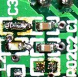
C3 and C4 bridges seem ok.
Any idea where to look and what to check for?
Thanks.........
Power seems ok (light comes on, chip warms up)
C3 and C4 bridges seem ok.
Any idea where to look and what to check for?
Thanks.........
Proper shorting and removal of board components.
Correct phase if you use electrolytic capacitors.
Try removing the caps, and connect inputs directly to source.
Ensure source outputs a signal.
If none of that helps I'm at a loss.
Correct phase if you use electrolytic capacitors.
Try removing the caps, and connect inputs directly to source.
Ensure source outputs a signal.
If none of that helps I'm at a loss.
Saturnus said:Try removing the caps, and connect inputs directly to source.
Do NOT do this! The Tripath inputs are biased at 2.5V. You must have the input caps in place.
All the other advice above is good. Let us know what you found. Also, see your email.
panomaniac said:
Do NOT do this! The Tripath inputs are biased at 2.5V. You must have the input caps in place.
Yeah, I should have mentioned "briefly". Mine didn't take any damage when I did it at least. Maybe just luck.
Volume Control
Did you replace the stock SI volume control?
If so, make sure that you wire the VR exactly as shown in the diagram. Insure that the last two wires coming from the board to the VR are not conencted if you replaced the VR.
If these wires are connected to the new VR as grounds - you will be shorting the input to ground. Thus no sound. Check the comnnections to your VR closely.
The Tripath chip is very resilient. Once you correct the problem it will make music.
Yes, I did replace the pot with an Alps. Forgot to mention this earlier.
And yes, the two last wires of the ribbon cable (opposite end to the switch wires) are not connected to anything. Right now, they are just hanging in the air.
Any more ideas?
And yes, the two last wires of the ribbon cable (opposite end to the switch wires) are not connected to anything. Right now, they are just hanging in the air.
Any more ideas?
Looking at your photo it is possible that your cap bridges are not good. With the amp on, touch each bridge with the tip of your finger. Do you get a hum or buzz in the speakers?
If you can not get your fingers in there, use a small bit of bare wire. The idea is to couple the noise picked up by your body into the circuit.
If you can not get your fingers in there, use a small bit of bare wire. The idea is to couple the noise picked up by your body into the circuit.
panomaniac said:Looking at your photo it is possible that your cap bridges are not good.
I found it far easier to bridge the cap gaps with a bit of tinned wire; just hold in place with a knife edge and touch with the iron.
Inputs???
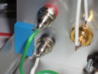
Did you add RCAs for the inputs directly to the Alps VR as in the diagram?
If so check what Panomaniac suggest (bridges) first. Then check the grounds with a multimeter to insure there is continuity from inputs to VR. VR to PCB. Input to speaker outputs.
As an aside are the small caps still there for the speaker outputs?
At one point I had not replaced mine at the outputs and I got no sound through my test piezo tweeters.
thanks guys. Here are the answers.....
Can't get any noise out of it at all, touching with a poined metal pin before or after C3
Yes....
cheks about 0 Ohms
checks about 0 Ohms
left + right channel identical:
RCA input(+) to speaker(+): 52.8kOhm
RCA input(+) to speaker(-): infinity
RCA input(-) to speaker(+): 16.7kOhm
RCA input(-) to speaker(-): infinity
additional checks (for whatever they are worth):
after input caps to before R1/R2 (checks the bridges): 1 Ohm each (so bridges are ok)
speaker(+) left to speaker(-) left: infinity (right channel identical)
RCA(+) left to RCA(-) left: 49.5kOhm (right channel the same)
The above checks were obviously done with the amp switched off
I replaced them with 0.1uF MKPs
Any other ideas?
Do you get a hum or buzz in the speakers?
Can't get any noise out of it at all, touching with a poined metal pin before or after C3
Did you add RCAs for the inputs directly to the Alps VR as in the diagram?
Yes....
check the grounds with a multimeter to insure there is continuity from inputs to VR
cheks about 0 Ohms
VR to PCB?
checks about 0 Ohms
Input to speaker outputs?
left + right channel identical:
RCA input(+) to speaker(+): 52.8kOhm
RCA input(+) to speaker(-): infinity
RCA input(-) to speaker(+): 16.7kOhm
RCA input(-) to speaker(-): infinity
additional checks (for whatever they are worth):
after input caps to before R1/R2 (checks the bridges): 1 Ohm each (so bridges are ok)
speaker(+) left to speaker(-) left: infinity (right channel identical)
RCA(+) left to RCA(-) left: 49.5kOhm (right channel the same)
The above checks were obviously done with the amp switched off
As an aside are the small caps still there for the speaker outputs?
I replaced them with 0.1uF MKPs
Any other ideas?
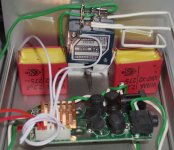
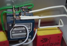
Well I think it's time for an overall picture of the setup and maybe some close-ups.... can't hurt!
Dont worry about it being tidy, my first attempts were awful!
Dont worry about it being tidy, my first attempts were awful!
As Lee says, maybe pictures will help us.
Or you may have to find an oscilloscope. Maybe the chip is not running - it happens.
No buzz when you touch near C3 is a bad sign.
Or you may have to find an oscilloscope. Maybe the chip is not running - it happens.
No buzz when you touch near C3 is a bad sign.
Another shot in the dark would be ensure that you have enough voltage on rails. The Tripath 2024 goes into self mute at around 9.2V, the T-amp would still show it to be on though (by the diode still being on).
- Status
- Not open for further replies.
- Home
- Amplifiers
- Class D
- t-amp stealth mod problem - no sound output at all...