Cast into a humble & simple question....
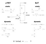
Gave away my Horowitz & Hill to my nephew (somesort of my clone actually), I'm stuck into how to calculate the final compound transconductance of a Sziklai pair consisting of a J-fet and a BJT. Any clue upward pointed appreciated.
Gave away my Horowitz & Hill to my nephew (somesort of my clone actually), I'm stuck into how to calculate the final compound transconductance of a Sziklai pair consisting of a J-fet and a BJT. Any clue upward pointed appreciated.
Attachments
Last edited:
Maple (link 1) or Mathematica (link 2) could help you derive a closed form analytical solution in a purely symbolic (non-numeric) chain of algebraic transformations.
Or it might be less expensive and more fun, to treat this as an approximation problem. One viewpoint is: there are three independent variables: Rdrain, Idss_jfet, Vpinchoff_jfet. To cover the domain space, run 3^5 = 243 LTSPICE simulations, at 5 different values of each of the 3 independent variables. Then grub around with zippy software to find an acceptable-to-you approximation formula (sometimes called: curve fitting) which matches the simulations, acceptably closely. i.e. the approximation function evaluated at the 243 datapoints, gives acceptable-to-you, small sum-of-squared-errors. Some curve fitting software (for example: Simfit, LabFit, MyCurveFit) is free, some costs USD 80 (e.g. CurveExpertProfessional), some is built into MATLAB if you've already got that package, and some costs USD 6000 (e.g. Belysa Immunoassay Curve Fitting).
Or it might be less expensive and more fun, to treat this as an approximation problem. One viewpoint is: there are three independent variables: Rdrain, Idss_jfet, Vpinchoff_jfet. To cover the domain space, run 3^5 = 243 LTSPICE simulations, at 5 different values of each of the 3 independent variables. Then grub around with zippy software to find an acceptable-to-you approximation formula (sometimes called: curve fitting) which matches the simulations, acceptably closely. i.e. the approximation function evaluated at the 243 datapoints, gives acceptable-to-you, small sum-of-squared-errors. Some curve fitting software (for example: Simfit, LabFit, MyCurveFit) is free, some costs USD 80 (e.g. CurveExpertProfessional), some is built into MATLAB if you've already got that package, and some costs USD 6000 (e.g. Belysa Immunoassay Curve Fitting).

perhaps calculate the dynamic input resistance R_π of the bjt as
R_π = β / g_m_bjt
then the dynamic resistive load on the jfet is
R_load = R || R_π
Then the voltage gain of the jfet stage is
A_jfet = g_m_jfet • R_load
So the total transconductance is
g_m_sziklai = A_jfet • g_m_bjt
(I denote by g_m what you denoted as S)
Does this work ?
R_π = β / g_m_bjt
then the dynamic resistive load on the jfet is
R_load = R || R_π
Then the voltage gain of the jfet stage is
A_jfet = g_m_jfet • R_load
So the total transconductance is
g_m_sziklai = A_jfet • g_m_bjt
(I denote by g_m what you denoted as S)
Does this work ?
Above I wrote
but I forgot to add the jfet current back in to the total; I think it should be
g_m_sziklai = A_jfet • g_m_bjt + g_m_jfet
So the total transconductance is
g_m_sziklai = A_jfet • g_m_bjt
but I forgot to add the jfet current back in to the total; I think it should be
g_m_sziklai = A_jfet • g_m_bjt + g_m_jfet
The BJT provides current gain to the JFET. The JFET's drain current and transconductance are each multiplied by the amount of current gain.
As an approximation, the current gain may be assumed to be constant. It is just the ratio of the total current to the JFET's current. The current gain will usually be set by R.
Ed
As an approximation, the current gain may be assumed to be constant. It is just the ratio of the total current to the JFET's current. The current gain will usually be set by R.
Ed
I broadly agree, but to be complete the influence of the B-E resistor should be taken into account: it steals some of the base current, including dynamically due to the dynamic resistance of the junction.
That said, with reasonable values, the effect should be minimal
That said, with reasonable values, the effect should be minimal
Considering small signals, the Vbe is constant, thus the current trough Rbe is constant too.
Dynamically irrelevant.
Dynamically irrelevant.
That's & onwards a very very very elaborate route...and more fun,
Very close, much appreciated! Munching on this matters, to continue...Does this work ?
Nice!!! Guard & close. Cheerio!I think it should be
Last edited:
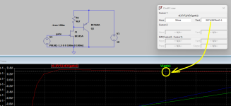
It's interesting is that this circuit is not very useful below about 10mA total current. It could be if the resistor was larger, but then the speed of the BJT is compromised. I chose 4k7 to be as large as I felt was useful for audio applications. Operating the FET at half Idss would require a resistor about 330 Ohms. It's interesting that the combination seems to be noticeably more linear than the FET alone.
postscriptum: 100% right. On the old euro plains the S ("siemens") is this very more general "g...m"actually(I denote by g_m what you denoted as S)
I doubt, & hence the OPis simply: S = gmxBeta, where gm is the transconductance of the JFET
granted & granted ... ehmm... towards? Well?As an approximation, the current gain may be assumed to be constant. It is just the ratio of the total current to the JFET's current. The current gain will usually be set by R.
- Home
- Design & Build
- Electronic Design
- Sziklai Transconductance calculation... ahum?