I want to sync two SG3525, clocked at 75Khz with a separate oscillator running at 85Khz. I plan on using two opto couplers connected to the sync pin of the 3525 with a resistor between the sync pin and +Vcc. Will this work reliably or do i need to use a buffer between the opto and the sync pin. Any info shared on this topic will be appreciated.
He loo.
The easiest and most reliable way to sync the SG3525 is to use
555 Chip, and supply it from the VREF pins connected (2+16) witch is 5V, and the output of the 555 to the SYNC pin of the SG3525.
And no need for any thing else.
The easiest and most reliable way to sync the SG3525 is to use
555 Chip, and supply it from the VREF pins connected (2+16) witch is 5V, and the output of the 555 to the SYNC pin of the SG3525.
And no need for any thing else.
Thanks mate.
But the issue here is that i want to sync the 3525 it to an external 85 Khz signal. As I'd much prefer keeping them isolated, I thought the best way of doing it was through an opto-coupler. Your thoughts on this will be appreciated.
But the issue here is that i want to sync the 3525 it to an external 85 Khz signal. As I'd much prefer keeping them isolated, I thought the best way of doing it was through an opto-coupler. Your thoughts on this will be appreciated.
Trevor-
The only Application Note I could find is one from Silicon General, PS-7, "Synchronizing the SG1525A PWM". Section 1 of this sheet (Synchronizing One Device to an External Clock) is as follows:
[A. Program the SG1525A oscillator with R(t) and C(t) to free-run at a frequency 10% slower than the external clock frequency.
B Drive the SG1525A SYNC pin terminal (pin 3) with the external clock. Input impedance is 2k. The clock amplitude should be greater than 2 volts and less than 5 volts. Pulse width should be at least 300nS for reliable triggering, but should not exceed the free-running oscillator clock pulse width by more than 200nS.]
Since you want to synch the '3525 at 150kHz, these times should not present a problem. If you were synch'ing it at the 300kHz, you might run into some problems, as the '3525 oscillator's max. frequency is ~400kHz.
EVA is right that there are some things that can't be learned from datasheets alone. I've looked everywhere for anything I can find on synch'ing the SG3525, MC33025, TL494, UC1846, and other popular PWM chips, and this Application Sheet is the best thing, by far, I have seen for the SG3525. I have worked on an "Application Note" of my own to consolidate the synch schemes for all of these chips so I can see them all at-a-glance. If I get some time, I will scan it and post it.
I got this sheet some time ago (before the www), so I have not gone to SG's website to see if it has made it into cyberspace yet.
Hope this helps,
Steve
Steve,
Thanks mate, that will surely help. Am also concerned about using an opto coupler between the two. Any schematic on how it is done reliably ?
Cheers
Thanks mate, that will surely help. Am also concerned about using an opto coupler between the two. Any schematic on how it is done reliably ?
Cheers
Happy to help out. Do the two '3525s need to be Galvanicaly isolated? If not, then you can sync 'em much easier w/o the opto. I wouldn't try to send a 75kHz signal thru the opto simply because if it's slow speed. I do not have any schematics or reference material on sync'ing thru an opto. If I can somehow scan the PS-7 App Note sheet and post it. I will try.
Thanks, a lot.
Yes the 3525 needs to be galvanic isolated from the sync clock. Hence the thought of using an opto. The speed of the opto is now a new worry that i have !!
Yes the 3525 needs to be galvanic isolated from the sync clock. Hence the thought of using an opto. The speed of the opto is now a new worry that i have !!
This might be a stretch, but you might try sending the sync signal through a small pulse transformer, with appropriate driving cktry.
pulling out thread from the dust ...
Hello all,
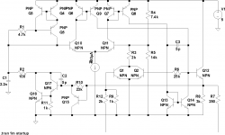
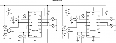
I find mistake in SG3525 datasheet, the comparator have wrong polarity transistors. I did simulation because still cant figure how to synchronize two or more of them. I have spice model for LTSpice, but i am not sure in accuration of the model in osc section.
I will do some tries, include hardware. But if someone have real circuit with use of these SYNC and OSC pins, i will be grateful ....
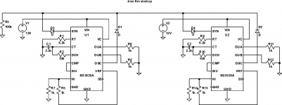
There is just an idea in second picture - terminate the slower cycle with pulse from fastest one. But still without this SYNC pin.
Hello all,
I find mistake in SG3525 datasheet, the comparator have wrong polarity transistors. I did simulation because still cant figure how to synchronize two or more of them. I have spice model for LTSpice, but i am not sure in accuration of the model in osc section.
I will do some tries, include hardware. But if someone have real circuit with use of these SYNC and OSC pins, i will be grateful ....
There is just an idea in second picture - terminate the slower cycle with pulse from fastest one. But still without this SYNC pin.
Attachments
Last edited:
- Status
- Not open for further replies.
- Home
- Amplifiers
- Power Supplies
- sync of SG3525