Hi all.
Which is design criterion for to determinate the value of the capacitor?
Self Blameless amp: 220R // 1uF
Ostripper FA2 amp: 100R // .68uF
Ostripper FA2S amp: 100R // .02uF
DestroyerX DX Blame ES amp: 220R // 220nF
MikeB Symasym5 amp: 33R // 100nF
Thanks
GEirin
Which is design criterion for to determinate the value of the capacitor?
Self Blameless amp: 220R // 1uF
Ostripper FA2 amp: 100R // .68uF
Ostripper FA2S amp: 100R // .02uF
DestroyerX DX Blame ES amp: 220R // 220nF
MikeB Symasym5 amp: 33R // 100nF
Thanks
GEirin
the resistor determines the bias current flowing through the driver stage.
The capacitor can be approximated by trial and error and listening.
I have seen [0r82+1uF]//R
There must have been a lot of trail and error to find that combination.
The capacitor can be approximated by trial and error and listening.
I have seen [0r82+1uF]//R
There must have been a lot of trail and error to find that combination.
Thanks Andrew
RC time constant and cutoff frequency
Self Blameless amp: 220R // 1uF --- 220 useg, 723Hz ---
Ostripper FA2 amp: 100R // .68uF--- 150useg, 1061Hz ---
Ostripper FA2S amp: 100R // .02uF --- 68useg, 2340Hz ---
DestroyerX DX Blame ES amp: 220R // 220nF--- 48,4useg, 3288Hz ---
MikeB Symasym5 amp: 33R // 100nF --- 33useg, 4822Hz ---
Other amplifier
Harman Kardon AVR745 --- 820useg, 194KHz ---
sorry for mistake
RC time constant and cutoff frequency
Self Blameless amp: 220R // 1uF --- 220 useg, 723Hz ---
Ostripper FA2 amp: 100R // .68uF--- 68useg, 2340Hz ---
Ostripper FA2S amp: 100R // .02uF --- 2useg, 79577Hz ---
DestroyerX DX Blame ES amp: 220R // 220nF--- 48,4useg, 3288Hz ---
MikeB Symasym5 amp: 33R // 100nF --- 33useg, 4822Hz ---
Other amplifier
Harman Kardon AVR745 --- 820useg, 194Hz ---
I use a triple output stage. I am using MJE15033/32's as the drivers. These have a 15 Ohm resistor connected emitter to emitter, and they then feed into the output devices. Originally, I had no base stoppers and therefore had stability problems in the output stage. Now I have 3.3Ohm base stoppers - no instability. So, my feeling is, if you run the driver stage hot and in class A with a very low emitter to emitter resistor (like 15 Ohms), and you use fast output devices, you can get away without a base charge suck-out capacitor.
There are more impedances into play than just the bias resistor (base input resistance and capacitance actually), and stored charge in the B-E junction, so time constants are much shorter.
The whole subject is difficult to understand without having done some experimentation with bipolar transistors used as switches, where base charge storage and removal phenomena become quite evident.
The whole subject is difficult to understand without having done some experimentation with bipolar transistors used as switches, where base charge storage and removal phenomena become quite evident.
Hi all.
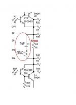
Here two types of speed switchoff capacitors.
First, the traditional R / / C. TC = RxC.
The second, Roender amplifier is more complex, with damping resistor + C. Here, how to calculate the TC?
Thanks.
Here two types of speed switchoff capacitors.
First, the traditional R / / C. TC = RxC.
The second, Roender amplifier is more complex, with damping resistor + C. Here, how to calculate the TC?
Thanks.
Attachments


I agree iwth Prof Leach. It is not neccessary if the driver stages are fully run in class A.
It also sounds better without the cap in the 2 amps I tried (including the DX Blame).***
*** Opinion alert!
It also sounds better without the cap in the 2 amps I tried (including the DX Blame).***
*** Opinion alert!
new tested values
FA2 and such are VERY old (first designs). New values for AX/PB120 are 150R/.33uF. Tested these on CRO .... smallest Xover "glitch". OPS is MJE15032/33 and NJW0281/0302 (ON semi).( Below 1) is tested for 12 hours 60V p-p square wave and thermally from ambient to over 100C - hairdryer 😀 (vbe stability <1mV change). Very "hardy" EF2. 🙂
OS
Attachments
bipolar transistors used as switches
Or while they are slewing at 100V/us. The cap and the driver/OP basestoppers are a big factor in how much transient "ringing" is produced. I did "trial and error" for the values in the schema above.
OS
Hi ostripper.
Thanks for your interest. My question is: if you can compare the same amplifier with two different capacitor switchoff speed. An amplifier with R / / C, and another amplifier (R + C) / / R. And know what sounds better. If there is a significant improvement in sound when using damping resistor. And finally, know what time constant circuit network used. I know how to calculate R / / C, but do not know how to calculate (R + C) / / R.
In your amp posted, C9 =.33 uf and R16 = 150R. TC = 0.0495 msec.
What is TC Roender amplifier?
I understand that this is done by trial and error to determine the values.
In short:
In short: What is the value of the constant time switchoff speed circuit that is pleasing to the ear?
In short: What is the value of the constant time switchoff speed circuit that is pleasing to the ear?
It is not just the constant of R/C but the Cob of the OP devices (3rd factor). My "trial and error" was with the square wave on the CRO. I do not know how to calculate the value of the R/C versus the Cob of the OP device. Actually , "R" is the driver current (a personal choice).
A 4 and 5th factor is the values of basestopper on both drivers and main outputs. I went for what gave me the best slew with minimum overshoot into a resistive load. (most accurate). I sure one can actually calculate the value versus Cob and that would depend on the device (datasheet). I have listened to many values (within reason - .1 - 1uF) of the "suckout/switchoff" cap and heard very little difference sonically , only what I could see (CRO).
OS
- Status
- Not open for further replies.
- Home
- Amplifiers
- Solid State
- Switchoff speed capacitor