Hello good people.
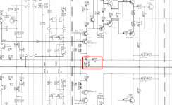
If increasing the size R232 lowers the cut frequency of the R232/C200 filter would be any advantage in increasing R232 to, say, 100 ohm? Doesn't that in theory provides cleaner supply?
On some amps you see RC filters for the Vas and input stages with 10ohm, and on others you see 100ohm and everything in between, with similar capacitances thus different cut off's.
Can this value mess with working parameters and, ultimately, sound qualities?
thanks.
Attachments
Last edited:
I worked on a Maplin mosfet amplifier that always hummed.
One fix was to do what you mention.
However another fix was to add a constant current source to the input LTP.
This stops rail modulating input signal.
Now when I design my amps I use both fixes.
One fix was to do what you mention.
However another fix was to add a constant current source to the input LTP.
This stops rail modulating input signal.
Now when I design my amps I use both fixes.
If increasing the size R232 lowers the cut frequency of the R232/C200 filter would be any advantage in increasing R232 to, say, 100 ohm? Doesn't that in theory provides cleaner supply?
In fitting filters to supplies there's not merely the cleansing of the input to consider, but also the output impedance. This is because opamps tend to create their own supply noise by virtue of classAB operation. The higher the supply impedance relative to their load, the more noise they'll make.
In the case of a Vas and LTP, normally they're running classA so the self-generated supply noise will be minimal. Hence supply cleaning is the primary function to be concerned about. Not so when powering opamps.Can this value mess with working parameters and, ultimately, sound qualities?
You do of course need to pay attention to the voltage drop across the series R. In my experience better filtering of supplies is one of the main ways of increasing SQ. I tend to do it by raising capacitance values though rather than increasing R values.
Last edited:
I find the same...........In my experience better filtering of supplies is one of the main ways of increasing SQ. I tend to do it by raising capacitance values though rather than increasing R values.
If you go back and read Leach's Lo Tim papers you will find he started with only small ceramic capacitors for local supply rail decoupling. Some of the amplifiers oscillated.
The cure was to introduce high esr electrolytics along with the ceramics for improved supply rail decoupling.
Most of the Forum's PCBs that I buy have fairly small electrolytics in the BoM list. I usually install the highest values that fit the space on the PCBs.
10ohm+diode+2200uF. Do not oversize the resistor. You will lose the contrast of the music, you will lose the impact of the music.
The dynamic impedance inside the diode does next to nothing to improve the RC performance.
It does do well to block reverse current flow when the output loads the supply rails.
It does do well to block reverse current flow when the output loads the supply rails.
And what values you tend to use in RC filtering?
thanks.
I use 56R and 100uF.
All LC filters contain some R (ESR in the caps and inductors) to provide some damping. Sometimes an explicit resistor is called for to achieve the optimum Q (normally 0.7).
The dynamic impedance inside the diode does next to nothing to improve the RC performance.
It does do well to block reverse current flow when the output loads the supply rails.
Does the diode really help in that respect? If so, how come it is not used in most well respected designs?
I like the idea, so i'm going to fit diodes in series with the Rs on my amp boards.
But does it really help? I suppose it is a nice feature to keep the front end voltage stable when the power rails are drugged down, but does it really matter, since the clipping headroom is ultimately defined by the output stage voltage?
but does it really matter, since the clipping headroom is ultimately defined by the output stage voltage?
Yes, if Output Stage is organized as "follower" - then drivers voltage could be 1.2 - 6V (or more if High Vgs, low transconductance Mosfets are used) above output stage - to use it (output stage) fully.
But why is it not used more often? Why isn't it a standard design practice, say like the the miller cap or the output zobel?
Any drowbacks maybe? Like the ~0.7 volt drop?
Any drowbacks maybe? Like the ~0.7 volt drop?
But why is it not used more often? Why isn't it a standard design practice, say like the the miller cap or the output zobel?
Any drowbacks maybe? Like the ~0.7 volt drop?
Yes 0.7V drop is a drawback. It is used in some designs (also in popular "VSSA" amp), but sometimes it is not much helpful, for example when VAS is bootstrapped, or supply rails does not "Sag" more than 0.1V under heavy loads, or in Class A amplifiers and so on.
I find the same.
If you go back and read Leach's Lo Tim papers you will find he started with only small ceramic capacitors for local supply rail decoupling. Some of the amplifiers oscillated.
The cure was to introduce high esr electrolytics along with the ceramics for improved supply rail decoupling.
Most of the Forum's PCBs that I buy have fairly small electrolytics in the BoM list. I usually install the highest values that fit the space on the PCBs.
High ESR electrolytics were chosen? Would that mean that currently available low ESR caps like Nichicon HE or Panasonic FR are not the best choices for supply rail decoupling?
I'd guess that high ESR was chosen to provide the right amount of damping of resonances involving the ceramic caps. In the absence of ceramics lower ESR caps will do a better job. Nichicon HE isn't particularly low ESR - for standard (non-polymer) electrolytics Nichicon HW is better, HZ is best but limited in maximum voltage to 16V.
Put a small cap ('bypass') in parallel with a big cap and in the middling frequency region you will probably have increased the total impedance. Bypass fans generally seem unaware of this. An electrolytic will usually maintain a low impedance across all of the audio spectrum, so can do audio decoupling/bypassing on its own -a bypass cap is both unnecessary and harmful.
However, sometimes we need to maintain a lowish impedance across a wider range, up to low to mid RF frequencies. In that case an electrolytic cannot do it unaided, so the solution is a properly engineered bypass. To damp the resonance created by the capacitive bypass and the inductive electrolytic you need highish ESR in the electrolytic.
However, sometimes we need to maintain a lowish impedance across a wider range, up to low to mid RF frequencies. In that case an electrolytic cannot do it unaided, so the solution is a properly engineered bypass. To damp the resonance created by the capacitive bypass and the inductive electrolytic you need highish ESR in the electrolytic.
My usual approach is to either not use a small parallel cap or to include a series resistor (about 1ohm) to damp any resonances with the main electrolytic. Would not need to be much higher with low ESL electro's.
- Status
- Not open for further replies.
- Home
- Amplifiers
- Solid State
- Supply RC filtering