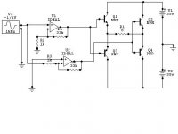
I can't see any differences from the classical bridge amplifier approach. You are generating two signals with opposite phase to drive comlementary output stages with the speaker in between them. This is how each "normal" bridge amplifier works.
This is fairly classic bridge designed commonly implemented in chip power amps. Has dissadvantages of (1) distortion generated in first opamp is increased by second opamp, and (2) output DC offset voltage of first amp stage is inverted by second stage. Thus in the event of a fault in upper section output transistors, the output DC voltage is inverted by the lower section, resulting in twice the destructive force to the load (your speakers). I prefer separate inverter stage as suggested by Stormo in the first post.
Cheers
Cheers
"This is fairly classic bridge designed commonly implemented in chip power amps. "
Name one using this circuit.
It doesn't work the way you think it does, its a Circlotron.
"Has dissadvantages of (1) distortion generated in first opamp is increased by second opamp, and (2) output DC offset voltage of first amp stage is inverted by second stage."
No one is holding a gun to your head, change the loop.
The X circuit (feedback scheme) from Pass will work well too.
So it is! Fancy me not noticing that... 🙄djk said:It doesn't work the way you think it does, its a Circlotron.
See that it has NPN transistors on the bottom row as well as the top, but it's not a quasi-complementary. Also, on the lower power supply rail the main filter cap just to the left of the bridge rectifier is reverse polarity;
 it should be positive to bottom as per the diodes feeding it.
There is another problem;
Inverting amp gain is 33k/1k
non - inverting amp gain is 1+33k/1k
So it's not exactly balanced as it stands, but it can be made to.
Inverting amp gain is 33k/1k
non - inverting amp gain is 1+33k/1k
So it's not exactly balanced as it stands, but it can be made to.
"There is another problem;
Inverting amp gain is 33k/1k
non - inverting amp gain is 1+33k/1k
So it's not exactly balanced as it stands, but it can be made to."
Have no idea what you are looking at.
The schematic clearly shows 300R + 3K0 for the non-inverting half and 300R + 3K3 for the inverting half, 26.84dB of gain.
Inverting amp gain is 33k/1k
non - inverting amp gain is 1+33k/1k
So it's not exactly balanced as it stands, but it can be made to."
Have no idea what you are looking at.
The schematic clearly shows 300R + 3K0 for the non-inverting half and 300R + 3K3 for the inverting half, 26.84dB of gain.
Hi djk
I was referring to Stormo's diagram above.
Even so, inverting and non-inverting gain is different if the same value resistors are used as in the diagram above.
I was caught out by the same thing recently, when adding and inverting two 120degree sine waves to create a 3phase output. I couldn't understand why the third output was lower than the other two.
In the non-inverting configuration, the input signal appears at the inverting input, and the gain given by the resistors is added to it. Hence the 1+ in the equation.
Had me stumped for a while
- Status
- Not open for further replies.
- Home
- Amplifiers
- Solid State
- superbridge ??