
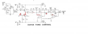

VR3 on the left is a center-tapped potentiometer. It may be difficult to find one. If you use a normal one, then the loudness button won't work, but everything else will still work fine (volume, balance, bass, treble).
I would not build this circuit because there are simpler circuits that work better. In particular, I don't like the first stage with Q1 and Q2. It's not well designed. Rather look for a circuit with 2 opamps and no transistors.
BTW, i you search for "Baxandall tone controls", you should find lots of similar circuits.
Good tone control schematic
Godfrey please give recommend a good schematic at your discretion.
thank you
VR3 on the left is a center-tapped potentiometer. It may be difficult to find one. If you use a normal one, then the loudness button won't work, but everything else will still work fine (volume, balance, bass, treble).
I would not build this circuit because there are simpler circuits that work better. In particular, I don't like the first stage with Q1 and Q2. It's not well designed. Rather look for a circuit with 2 opamps and no transistors.
BTW, i you search for "Baxandall tone controls", you should find lots of similar circuits.
Godfrey please give recommend a good schematic at your discretion.
thank you
Last edited:
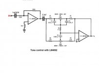
Download datasheet of LM4562. You will find one tone control circuit there. Connect one LM4562 as a buffer at the input of this circuit.
As best as it gets with a bonus... easy to construct.
Gajanan Phadte
As best as it gets with a bonus... easy to construct.
Gajanan Phadte
Download datasheet of LM4562. You will find one tone control circuit there. Connect one LM4562 as a buffer at the input of this circuit.
As best as it gets with a bonus... easy to construct.
Gajanan Phadte
Do you think this should look:
Attachments

One of the 100K in buffer seems wrongly drawn.
Use dual, good quality supply with proper bypassing near the 4562.
Gajanan Phadte
Use dual, good quality supply with proper bypassing near the 4562.
Gajanan Phadte
Last edited:
One of the 100K in buffer seems wrongly drawn.
Use dual, good quality supply with proper bypassing near the 4562.
Gajanan Phadte
You must mean this to be:😉
Attachments
One of the 100K in buffer seems wrongly drawn.
Use dual, good quality supply with proper bypassing near the 4562.
Gajanan Phadte
finally have this (tutto completto😉):
Attachments
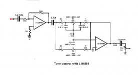
That looks OK, but I'd put the volume control at the input, not the output.
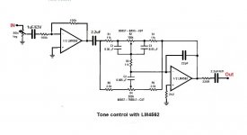
You mean like this!😉
What is the difference?😕
Attachments
Last edited:
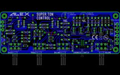
Very good PCB
I need my PCB (botton layer, R=1:1) in pdf for that can made this control.
A big thanks to Alex!
Best Regards,
Cheers!
....... and PCB for first schematic .....😀
Regards Alex
I need my PCB (botton layer, R=1:1) in pdf for that can made this control.
A big thanks to Alex!
Best Regards,
Cheers!
Last edited:
Just interested- why the volume control before tone circuit I personally would put it after as it helps keep the noise floor down at lower volume levels. You can always put a unity gain buffer after the volume if output impedance is an issue?
I need my PCB (botton layer, R=1:1) in pdf for that can made this control.
A big thanks to Alex!
Best Regards,
Cheers!
Insert the image into something like LibreOffice and then save it as a pdf.
Attachments

Yes, I was thinking output impedance would be too high, especially with a 50K pot, but you're right about the noise too. If the pot's not mounted on the PCB, then he can try wiring it up both ways and decide which he prefers.Just interested- why the volume control before tone circuit I personally would put it after as it helps keep the noise floor down at lower volume levels. You can always put a unity gain buffer after the volume if output impedance is an issue?
Actually, there is another problem with putting the pot at the output: If the input is a high level signal and the tone controls are set to max boost, then the second opamp may clip the signal.
Yes, I was thinking output impedance would be too high, especially with a 50K pot, but you're right about the noise too. If the pot's not mounted on the PCB, then he can try wiring it up both ways and decide which he prefers.
Actually, there is another problem with putting the pot at the output: If the input is a high level signal and the tone controls are set to max boost, then the second opamp may clip the signal.
At the entrance I want to use CD and DVD - player.🙂;😉
Insert the image into something like LibreOffice and then save it as a pdf.
The picture does not contain only the tracks...so won't work
Gajanan Phadte
- Status
- Not open for further replies.
- Home
- Source & Line
- Analog Line Level
- Super tone controls-I need PCB