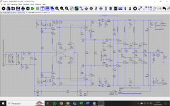
Esse circuito de amplificador super simétrico aplica boas técnicas discutidas aqui no forum.
Essa topologia de circuito é a mesma aplicada na tese de mestrado do Professor Leach.
McIntoch, Rotel e outros aplicam a mesma topologia de circuito em seus amplificadores de estado sólido.
Agradeço por comentários relacionados com melhorias nesse amplificador. Corrente de bias é um parametro que pode ser escolhido pelo montador.
(Comentários em ingles pelas regras do forum).
This amplifier idea uses good technical ideas discussed here.
The circuit toppology is the same used by Leach in this master tesis.
McIntoch, Rotel and others makes uses the same circuito topologies in his solid state amplifiers.
I appreciate comments concerning improvements of this amplifier. Bias current is a parameter each one can choose and it wil not improve this amplifier as it is a option of the amplifier maker.
Regards
Attachments
Last edited:
Hi Ed.
Your doc is just a point of view. I preffer minimum bias to avoid crossover distortion with low idle heating. High bias tend to create more distortion in OS and it can be confirmed with good and real DHT tester with resistive load.
Thank you for your comment.
I also got improvements adding offset adjustment. I will also add over current protection to avoid a big money loss in case of accident in output as a short circuit (of course with no performance loss).
Ronaldo
Last edited:
The optimal bias is what the simulator says it is. 🙂
The problem with underbias is that distortion is increasing very rapidly. In contrast, overbias leads to only moderate increases in distortion. Since the bias current will vary with temperature, it is better to be on the less steep part of the graph.
Ed
The problem with underbias is that distortion is increasing very rapidly. In contrast, overbias leads to only moderate increases in distortion. Since the bias current will vary with temperature, it is better to be on the less steep part of the graph.
Ed
The optimal bias isn’t what the simulator says it is - it’s what the spectrum analyzer says it is. May or may not be the same.
EF3’s are somewhat tolerant of underbias, though. Takes hardly any current at all for gross distortion to go away. It will keep getting better till it hits an optimum, but you may get where you don’t care anymore before that happens.
EF3’s are somewhat tolerant of underbias, though. Takes hardly any current at all for gross distortion to go away. It will keep getting better till it hits an optimum, but you may get where you don’t care anymore before that happens.

The optimal bias for 0.22 Re is about 100mA. My simulation agrees that.
For minimum bias, you may consider CFP. It’s optimal bias is around 10~20mA.
For minimum bias, you may consider CFP. It’s optimal bias is around 10~20mA.
Entendo que a simulação de circuitos é uma ferramenta fantástica e ajuda muito a entender o funcionamento e as suas limitações. Por isso, sempre faço simulações antes de partir para a montagem dos circuitos que é muito trabalhosa e cara.
Entendo também que sempre existirá diferença entre resultados de simulação e o circuito montado com componentes reais.
Por isso escrevi sobre testes com circuito real e bons analisadores de distorção. O resultado da simulação é sempre otimista em relação a realidade.
Por isso não considero as argumentações dos colegas válidas e continuo aplicando 40mA a 60mA de corrente de bias por par de saída.
A escolha pelo arranjo EF3 foi pela confiabilidade desse circuito. O arranjo CPF apresenta problemas de estabilidade que muitas vezes são difíceis de corrigir.
Toda conclusão tirada com simuladores deve ser muito bem analisada considerando a confiabilidade do simulador e principalmente dos modelos de transistores (LIBs) usados.
---
I understand that circuit simulation is a fantastic tool and helps a lot to understand how it works and its limitations. That's why I always do simulations before starting to assemble the circuits, which is very laborious and expensive.
I also understand that there will always be a difference between simulation results and the circuit assembled with real components.
That's why I wrote about tests with real circuits and good distortion analyzers. The simulation result is always optimistic in relation to reality.
That's why I don't consider my colleagues' arguments valid and I continue to apply 40mA to 60mA of bias current per output pair.
The EF3 arrangement was chosen because of the reliability of this circuit. The CPF arrangement presents stability problems that are often difficult to correct.
Any conclusions drawn with simulators must be carefully analyzed considering the reliability of the simulator and especially of the transistor models (LIBs).
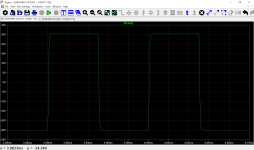
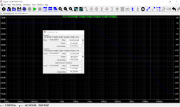
More informations to conclude the first part of this amplifier project.
Next step is add offset corrections and over current protection.
Here we have step response and phase margin result of open loop gain of amplifier.
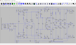
Next step is add offset corrections and over current protection.
Here we have step response and phase margin result of open loop gain of amplifier.
Attachments
No, that statement is not correct.51mA is too low for 0.22ohm emitter resistors. See my article on Class AB biasing.
Ed
Depending on how many transistors you parallell in your output stage that optimal bias point you are hunting for will vary.
The more you parallell, the lower the optimal bias point will be.
Then it also is a matter what the designer of the amplifier think is the best sound of distortion components and character.
You can tune bipolar transistors for odd order preference and a more linear distortion preference and you need to find the right amount of mixing amount of parallell pairs, amount of bias and the value of the resistor itself.
There is no "perfect" or "optimal".
Depends on what you are looking for as a designer and what sound character you want.
Last edited:
That is true only if the total bias current is approaching class A. For normal class AB biasing, paralleling two or four pairs of transistors has little effect on the per-transistor bias for lowest distortion.flex2 said:Depending on how many transistors you parallell in your output stage that optimal bias point you are hunting for will vary.
The more you parallell, the lower the optimal bias point will be.
Ed
No, that statement is not correct.
Depending on how many transistors you parallell in your output stage that optimal bias point you are hunting for will vary.
The more you parallell, the lower the optimal bias point will be.
What it really is the more you parallel, the lower per transistor you can get away with before you reach diminishing returns. That assumes you scale Rbe DOWN, which increases driver bias current.
There is no concense related as bias current, so it is becoming a amplifier maker choice.
I explain a technical and pratical method used in amplifier development and it was no criticed as it is correct and used to all makers to define the correct bias point in product development. Just remember - the amplifier must be warmed to define the best bias point - it take some time in the project development.
If there is no serious comments to improve this amplifier project, I will give up from this project. If some one decide try it I will help.
With kindest Regards.
Ronaldo
Last edited:
- Home
- Amplifiers
- Solid State
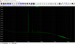
- Super Symmetrical Amplifier with THD = 0.003111% for 8 Ohms load