Hi,
we are looking forward to a 1:10 high-voltage step-up transformer. The application is in a physics laboratory.
The input(primary) will be driven with up to 150V from this amplifier: https://www.falco-systems.com/High_voltage_amplifier_WMA-300.html
and up to 1.5kV is the desired output voltage.
The load is a high impedance sample of a least 10MOhm and we are working typically between 500 to 20-30kHz.
It would be great if a specialist out here could give me a suggestion.
Thanks
GM
Thanks, isolation is required. Depending on the experiment the sample/load should be floating.
From my quick look at mouser, the secondary rating is limited to 280V. Maybe some special transformers which are used in valve amps, do have the required high secondary voltage rating?
From my quick look at mouser, the secondary rating is limited to 280V. Maybe some special transformers which are used in valve amps, do have the required high secondary voltage rating?
Do you have equipment to wind on your own? I'm tempted to attempt the design challenge. But first, confirm or answer the following:
-Input impedance is 50R and can vary if needed.
-No DC current available
-500Hz to 20-30kHz at 0dB or roll-off at extremeties available
-How much Rdc losses allowed?
-How critical is core linearity choice?
-What kind of waveforms? Sine only, or square/triangular as well?
-Input impedance is 50R and can vary if needed.
-No DC current available
-500Hz to 20-30kHz at 0dB or roll-off at extremeties available
-How much Rdc losses allowed?
-How critical is core linearity choice?
-What kind of waveforms? Sine only, or square/triangular as well?

A regular, good quality, low to medium power output transformer used in reverse should work: if it is designed to pass 30Hz, it will handle a voltage 500/30 times higher at 500Hz.The 30kHz upper limit is easily manageable too.
I see two possible issues:
-The primary isolation is not aimed at 1.5kV, but a well-built OT should be able to handle it without too many problems
-To arrive at a 1:10 voltage ratio, the impedance should be 1:100; for a 16ohm transformer, it would mean a primary impedance of 1600ohm, which is on the low side, but probably findable; alternatively, you could lower the primary voltage to arrive at a larger ratio, like 1:15 or 1:20
for
I agree. Hammond shows Hipot testing for 2000 and 3500 volts. Yeah you aren't using the transformer as intended but oh well.
A regular, good quality, low to medium power output transformer used in reverse should work: if it is designed to pass 30Hz, it will handle a voltage 500/30 times higher at 500Hz.The 30kHz upper limit is easily manageable too.
I see two possible issues:
-The primary isolation is not aimed at 1.5kV, but a well-built OT should be able to handle it without too many problems
-To arrive at a 1:10 voltage ratio, the impedance should be 1:100; for a 16ohm transformer, it would mean a primary impedance of 1600ohm, which is on the low side, but probably findable; alternatively, you could lower the primary voltage to arrive at a larger ratio, like 1:15 or 1:20
I agree. Hammond shows Hipot testing for 2000 and 3500 volts. Yeah you aren't using the transformer as intended but oh well.
It depends on the requirements. My impression is that 500Hz and 30 KHz are just limits for the measurements, not limits of the transformer. That is quite a difference. If want to pass near perfect 30KHz square waves it will need some 200KHz bandwidth or better.....The 30kHz upper limit is easily manageable too.
Get a good quality 240x to 24v transformer and turn it around! Put 240v into the 24v winding and you’ll get 2400 out. You can adjust it by choosing the right primary and secondary voltages of the transformer. By careful as it can kill you fast and easy!
Two other solutions that come to my mind are: use a tube like 6HV5A with 1:1 bifilar transformer. The 6HV5A running at 2-2.5 KV 10-12mA would require some 130-150H minimum to provide 1500V peak at 500Hz with low distortion. Getting wide bandwidth from 1:1 bifilar is "easier". It cannot be the usual audio interstage transformer of course, starting from the insulation requirements but wires exist in different flavours.....
Zout would be in the same ballpark of 50R generator with 1:10 transformer.
https://frank.pocnet.net/sheets/123/6/6HV5A.pdf
The other solution could be a fully DC coupled circuit using the same high voltage tubes but in an AUGMENTED cathode follower which, unlike the name might suggest, can have voltage gain:
https://www.labjc.com/wp-content/uploads/2021/02/040CathodeFollower-1.pdf
But this needs some further thinking and assessment.
Last edited:
Surely you are not serious? The core would saturate.Get a good quality 240x to 24v transformer and turn it around! Put 240v into the 24v winding and you’ll get 2400 out. You can adjust it by choosing the right primary and secondary voltages of the transformer. By careful as it can kill you fast and easy!
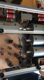
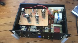
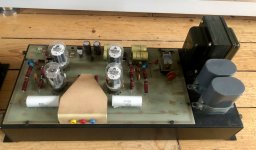
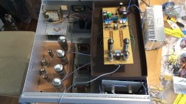
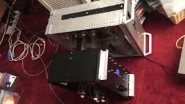
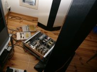
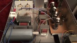
What are you driving? Electrostatics?I use a Mu Follower stage with PL519 tubes @ 2,5kV swing.
A Zotl amp is also an option.
Yes, electrostatics.What are you driving? Electrostatics?
Attachments
One could also cascade two transformers, such as 1:3,33 driving another 1:3,33. Transformers closer to unity transfer ratio are easier to optimize in terms of capacitance.
Shouldn't saturate, as it will be used for 500Hz instead of 50Hz. It is the HF response that will be questionable.
Surely you are not serious? The core would saturate.
Shouldn't saturate, as it will be used for 500Hz instead of 50Hz. It is the HF response that will be questionable.
Yes, electrostatics.
(Off topic)
Direct drive, wow. One day I will also build one. That day is still far away.
- Home
- Amplifiers
- Tubes / Valves
- suggestions for a 1:10 high voltage step-up transformer