Hey folks,
I am trying to fix this amp and having quite a lot of difficulty. I cannot find a schematic (it's not the old vintage A21!), and the PCBs are completely unmarked with polarity or component numbers - great fun. The left power amp is working perfectly, and both preamps are working great. The right power amp however has problems, when connected to the dim bulb, it constantly goes very bright and then dull, over a 2-5 second cycle. It's a little random, not a perfect rhythm - sometimes it will stay dull for a few seconds before going bright again. There is a little diode on the right power amp board that lights up dimly in sync with the dim bulb tester. The one on the left side does NOT light up at all.
After about 10 seconds, the relays turn on on the amp and I can measure DC on the outputs, which is going above 10v when the bulb goes bright and then dropping down when it goes dim - rinse and repeat. Any dc voltage measurements I've tried to take on any components is following the same loop - fluctuating between very low and very high. There are resistors across the output ICs however, which I'm thinking might be idle current resistors - on the good amp (left) these are measuring 0.0v when placing the probes on either side of the resistors. On the bad amp - I'm getting 0.6v across them.
It looks like this amp has been messed with in the past, on the right channel too - the screws that screw the outputs in to the heatsink are not the flathead ones in the left side, but rather over-long philips screws. One of them was bent. That's about all the info I can provide...
Things I've done to the right channel so far...
- Replaced the two C3284 outputs (one of them registered as a diode on my component tester, but neither were shorted and tbh I think this was a misread from the reader)
- Replaced one of the two 10000uf filter caps - it was measuring ok but it was noticeably bulging at the top and bottom
- Removed and tested EVERY SINGLE transistor and tested them with my component tester - all registered fine, but I recognise this doesn't guarantee they are. I can say that I also tested them all with my diode meter and got no shorts or worryingly low readings
- Removed and tested EVERY SINGLE capacitor - all fine apart from one 10uf cap which was slightly off (8.2uf, 2% voltage drop and 2.5ohm ESR), which I replaced.
- Tested all diodes in circuit - got beeps in one direction and OL in the other.
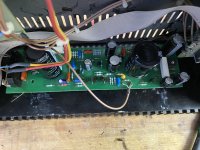
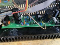
Attached are some photos of the right power amp (fuse removed in photos, but yes I've been testing it with a fuse). The bridge measures ok with diode test, and i don't see how it could be that because everything after it in the circuit is getting power? The link you sent is for a much older unit. this is the comparatively modern A21SE
Attachments

Without circuit diagrams it is difficult, more so when you haven't got it in front of you...
My first thought is that I wouldn't expect this to work with a bulb tester because these things draw lots of current and run super hot by design. So a bulb will kill the supplies and the bulb as you observe it going bright and dim is perhaps not unexpected.
You say one channel is OK. Have you listened to that channel? and does that channel run hot hot hot? (it should)
Could the channel causing the bulb to fluctuate actually be the good channel?
Which version is it?
This or this?


My first thought is that I wouldn't expect this to work with a bulb tester because these things draw lots of current and run super hot by design. So a bulb will kill the supplies and the bulb as you observe it going bright and dim is perhaps not unexpected.
You say one channel is OK. Have you listened to that channel? and does that channel run hot hot hot? (it should)
Could the channel causing the bulb to fluctuate actually be the good channel?
Output IC's? What are you looking at here?There are resistors across the output ICs
Which version is it?
This or this?

СhiFi
Measure the voltage on the electrolytics after the rectifier (without a fuse).
Measure the voltage on the electrolytics after the rectifier (without a fuse).
Attachments

Last edited:
Do you have an original or a clone?
https://forums.melaudia.net/showthread.php?tid=10956
https://aliexpress.ru/item/10050040...w.productlist.search_results.3.1acc4aa6cxeJpN
https://forums.melaudia.net/showthread.php?tid=10956
https://aliexpress.ru/item/10050040...w.productlist.search_results.3.1acc4aa6cxeJpN
Last edited:
It's the silver one (left). It has C3284 transistors screwed into the heatsink.
My first thought is that I wouldn't expect this to work with a bulb tester because these things draw lots of current and run super hot by design. So a bulb will kill the supplies and the bulb as you observe it going bright and dim is perhaps not unexpected.
You say one channel is OK. Have you listened to that channel? and does that channel run hot hot hot? (it should)
Hmm interesting... I will listen to left channel tomorrow with fuse out on right channel and report back - it would be hilarious if this is where I've gone wrong! Thanks so much for the great tip. If the left channel is not working - would you advise testing right channel without dim bulb to see what happens and face potential burning?
It is a valid approach in the world of fault-finding when you reach a point where you can find nothing wrong.If the left channel is not working - would you advise testing right channel without dim bulb to see what happens and face potential burning?
Nice 🙂 I know someone with two Sugden systems and one of each amp.Original
It was one of the worst amplifiers I ever worked on... it seemed like it was assembled in a shed... with huge misalignments (mechanical) and a badly designed... underrated / not heatsinked flatpack bridge rectifier...
The only reason I touched it was the fact that it belonged to a good friend of mine... but he had nothing but trouble with this amp. One channel was cutting intermittently... and after a lot of poking around - it turned out to be a bridge rectifier fault (!!)... NOTE: it was measuring okay, but failing under the heavy current load in operation.
Later, the speaker relay developed an intermittent fault as well... I cleaned its contents a few times but in the end, I used a higher-quality relay replacement... the split contacts' relay...
I modified it... elna input selector switch, TKD pot, and annealed silver ribbons to the switch for two inputs... larger power supply caps as well... He liked the sound a lot...
The recent issues from Sugden are probably much better...
Yes, I replaced it with the highest rating one I could find ... It was the same voltage, but 4A one... and it worked okay for many years.
Did you notice the part where I said the dc on the right channel outputs was going above 10vdc before every reset?is a valid approach in the world of fault-finding when you reach a point where you can find nothing wrong.
Yes, however the amp is AC coupled at the speaker output and so I'm not so concerned at what happens there DC wise, not at this point anyway. The first thing has to be to get the amp powered up with the rails stable.Did you notice the part where I said the dc on the right channel outputs was going above 10vdc before every reset?
Provided this area of the circuit which is a constant current sink is OK then the current is limited. You should be able to safely power if so.
The vital voltages to measure are the main rail and the midpoint voltage which is the collector of the lower 2SC3284 output transistor. That point should be approx half the supply voltage.

The vital voltages to measure are the main rail and the midpoint voltage which is the collector of the lower 2SC3284 output transistor. That point should be approx half the supply voltage.
I tested the left channel - nothing. The dim bulb also goes completely dark after initial power-on, which i suppose it probably shouldn't if the power amp draws so much power. So... I tested the right channel without dim bulb as suggested and... after 5 seconds the fuse (2.5a) in that channel blew. I guess that means I have two faulty channels with opposite problems!
Maybe I should swap this one out then, thanks for the tip!it turned out to be a bridge rectifier fault (!!)... NOTE: it was measuring okay, but failing under the heavy current load in operation.
+1It was one of the worst amplifiers I ever worked on... it seemed like it was assembled in a shed... with huge misalignments (mechanical) and a badly designed... underrated / not heatsinked flatpack bridge rectifier...
The only reason I touched it was the fact that it belonged to a good friend of mine... but he had nothing but trouble with this amp. One channel was cutting intermittently... and after a lot of poking around - it turned out to be a bridge rectifier fault (!!)... NOTE: it was measuring okay, but failing under the heavy current load in operation.
Later, the speaker relay developed an intermittent fault as well... I cleaned its contents a few times but in the end, I used a higher-quality relay replacement... the split contacts' relay...
Je l'ai modifié... sélecteur d'entrée elna, potentiomètre TKD et rubans en argent recuit sur l'interrupteur pour deux entrées... bouchons d'alimentation plus grands également... Il aimait beaucoup le son...
Les numéros récents de Sugden sont probablement bien meilleurs...
View attachment 1181109
View attachment 1181110
View attachment 1181113
- Home
- Amplifiers
- Solid State
- SUDGEN A21SE Repair