Been building an amp around 2 of these for what feels like forever:
UPC1342V 2SC5200 2SA1943 220W Mono Power Amplifier Board Kit HiFi Class A Amp | eBay
(not from ebay, but its the same kit from China)
All was going well (after a few smoke/fire 'learning' moments), had it working for a good couple of weeks while I waited for a few last parts, more heatsinks etc.
As i came to test it prior to my absolutely final re-assembly, the left amp board gives out a very load buzzing, accompanied by a hefty pop when power is cut. The right side amp seems to be fine and plays audio as before.
I've eye-balled the PCB and it looks fine, tried the other power from the transformer and switched inputs and outputs around to the point I am confident the issue is the PCB.
2 things that could have caused an issue. there's a chance a shred of metal from heatsink drilling got in there somewhere, although I cleaned it with compressed air before I powered it up with that in mind.
the other ****-up i made...in the case, i have a PCB for the volume pot about 5mm above one if the caps on the amp, and this 'slipped' and was probably touching the top of the cap, I dunno if electrical contact was made, or if damage could have been caused if there was.
Could this have caused permanent damage? or anything I can do to check it before I order another amp PCB (my 4th!)
This amp's circuit is quite simple, if not the few small cap problem then it must be the driver ic upc1342V problem.
Please took some pics of your amp setup, try to see if we can find something wrong.
Please took some pics of your amp setup, try to see if we can find something wrong.
not sure how the images are going to display:
this is the amp fixed to heatsink

bottom of the board

this is how it could have been damaged, the board was resting on the cap when I powered up:

part which is resting on the cap looks to be the case of the larger black component:

Finally, how she looked when she was working :
:

this is the amp fixed to heatsink
bottom of the board
this is how it could have been damaged, the board was resting on the cap when I powered up:
part which is resting on the cap looks to be the case of the larger black component:
Finally, how she looked when she was working
:
Last edited:
when you post, go advanced, select pics and remember select the upload before you final post
are they showing now patrick? I hosted them on google first, didnt seem to work, now changed to imgur.
pics showing now
1. the volume PCB with preamp ?
2. you connect the speaker output to protect circuit or direct to output post
1. the volume PCB with preamp ?
2. you connect the speaker output to protect circuit or direct to output post
volume PCB connects to the preamp inputs board at the back of the case, and is powered by the board above the broken amp PCB.
At the moment the preamp isn't connected at all, but i still get the buzzing to the speaker regardless.
I don't have a protect circuit, so in the few times I've tested it, it's been straight to the speaker...
At the moment the preamp isn't connected at all, but i still get the buzzing to the speaker regardless.
I don't have a protect circuit, so in the few times I've tested it, it's been straight to the speaker...
Do you connect the both PCB ground to the case
I was actually trying to work out how to do this at the time, I connected the gnd from the power-in to the case, as I thought was the norm, but I didn't do anything additional to the amp pcb directly.
the two PCB ground should connected to a single point of the case and the connection should be short and same distance from each PCB will be best fit
you mean you connected the ac input ground to the case only
erm...yeah, actually now that i think about it, the first time I had issues was the first time the gnd was connected to the case and the pot pcb may have been shorting to the top of the amp cap at the same time.
the two PCB ground should connected to a single point of the case and the connection should be short and same distance from each PCB will be best fit
I thought since the PCB is screwed into the case, that would ground them, but looking at the PCB more closely, it seems the screw holes arent connected to anything.
Is this likely to be the cause of the problem, the right side PCB is currently working fine, with or without the gnd wire connected to the case.
Amp internal circuit must need a suitable grounding, otherwise different kinds of noise will be introduced to your amp.
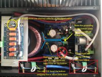
Maybe the ac input cable on the top PCB introduced noise to your amp, you may move that PCB close the power transformer.
Maybe the ac input cable on the top PCB introduced noise to your amp, you may move that PCB close the power transformer.
Last edited:
the pot pcb may have been shorting to the top of the amp cap at the same time.
you should use something like a thin plastic sheet to isolate them.
Amp internal circuit must need a suitable grounding, otherwise different kinds of noise will be introduced to your amp.
Maybe the ac input cable on the top PCB introduced noise to your amp, you may move that PCB close the power transformer.
I'm a little confused how I would do this, could you direct me to a picture of it in practice?
Thanks for all your advice so far by the way, very appreciated!
I'm a little confused how I would do this, could you direct me to a picture of it in practice?
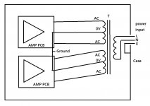
I point out the points for the connection layout
Attachments
still confused 😕
so I should connect the 2 Ov from the transformer together and to the case as per your diagram, and also wire the ground from the power-in to the case?

I added this at the back of the case just before the issues started, but since a number of other things changed at the same time I wasnt sure if it was better or worse for it.
so I should connect the 2 Ov from the transformer together and to the case as per your diagram, and also wire the ground from the power-in to the case?
I make this diagram, hope you can understand how to wire the ground.
Just connect the "PCB 0v" to the ground where I point out before.
How to ground inside the amp is not easy to explain, not just simple 0v connect to ground, please google more info about it.
Attachments
Last edited:
The problem channel speaker output cable(red cable) too close to the input cable(white cable), better keep them some distance apart
- Home
- Amplifiers
- Solid State
- sudden loud buzzing from my 2SC5200 / 2SA1943 amp