H
HAYK
Error correcting feedbacks compare the weighted output with the input and feedbacks only the error. It is possible to correct in open loop by subtracting/adding the difference with a bridged amplifier.
Here is another way of subtracting with very little feedback.
The error is already between the inputs, it is added to the negative input after inverting. By this what was lacking in the output is add. Due to slight feedback, it is amplified by only 1.057 to near perfect cancelation.

This is a lm3886 model with a gain of 26db. Stand alone, it has a noise of 5.5mv in 20-20khz BW. By subtraction, it becomes 32uv. This is 180 times reduction in anomalies. The circuit as is, is unstable as it also increased the frequency response.
In real world, using NE5534 as differential, it needed a gain of 1.31 for minimum noise of 120uv and reduction in gain to set it back 26db. A capacitor made the circuit stable.

Here is another way of subtracting with very little feedback.
The error is already between the inputs, it is added to the negative input after inverting. By this what was lacking in the output is add. Due to slight feedback, it is amplified by only 1.057 to near perfect cancelation.
This is a lm3886 model with a gain of 26db. Stand alone, it has a noise of 5.5mv in 20-20khz BW. By subtraction, it becomes 32uv. This is 180 times reduction in anomalies. The circuit as is, is unstable as it also increased the frequency response.
In real world, using NE5534 as differential, it needed a gain of 1.31 for minimum noise of 120uv and reduction in gain to set it back 26db. A capacitor made the circuit stable.
H
HAYK
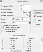
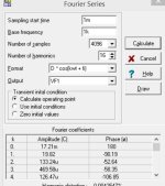
I introduced a distortion to the chip of 0.016% and applied error corrector to get 0.004% with a error gain of 1.5. I don't understand why it doesn't get subtracted completely. Maybe the capacitors required to limit the error correction frequency is the problem.

Attachments
H
HAYK
I think what you are describing is a form of 'feed forwards' error correction.
This was a big area of R&D in RF amplifiers about 20 years ago, although AIUI, it has a long history.
See also 'pre-distortion'.
It may be conceptually easier at RF, because the bandwidth is generally some fraction of an octave instead of 3 decades of audio.
One flavour is to distort the signal before it leaves the DAC.
A lot of people much cleverer than me spent a lot of effort on this, many of them are probably still at it.
For complete cancellation, the error correction signal must be very precise. For example, to correct the error by a factor 100, 40dB, your error signal must be accurate to 1/100, 1%. For 60dB correction the error signal must be 0.1% accurate.I don't understand why it doesn't get subtracted completely.
You get into all kinds of issues like resistor and cap accuracy and opamp deviations from ideal infinite gain and all of that is also frequency dependent due to parasitics.
That is why this technology is used very little - global feedback does not have these issues.
Also, many variants of error correction are negative feedback in disguise and can be shown to be equivalent.
But it's interesting to play with this stuff.
Jan

H
HAYK
I looked the feed forward error correctors, they all need extra output to add/subtract the error in parallel current ot bridged.
The loop gain of lm3886, has 24db NFB@20Khz. With corrector of gain 1.31, it gets 51db. The opamp used with such low gain, doesn't require super opamps, the low cost NE5534 with offset adjust is excellent for this use.
By this corrector it will be possible to get a high quality amp for low cost.
The loop gain of lm3886, has 24db NFB@20Khz. With corrector of gain 1.31, it gets 51db. The opamp used with such low gain, doesn't require super opamps, the low cost NE5534 with offset adjust is excellent for this use.
By this corrector it will be possible to get a high quality amp for low cost.
Attachments
H
HAYK
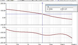
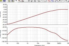
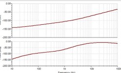
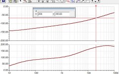
In fact the corrector is working decreasing the output error by 35 fold.I injected 100mv 1khz in series with the output where the input is shorted. Without corrector I have 250uv left by the local feedback, with corrector, it becomes 7.5uv. Bellow are the graphs of attenuation with local feedback alone and with corrector.
In this case the opamp is not working in differential mode.
I am still scratching my head, from where comes the 1.31 gain is needed.
In this case the opamp is not working in differential mode.
I am still scratching my head, from where comes the 1.31 gain is needed.
Attachments
H
HAYK
These are ideal components in a sim. Practical implementation makes getting these figures all but impossible.
If you consistently got 20 dB distortion in a practical amp, I’d say you would have done a good job!
If you consistently got 20 dB distortion in a practical amp, I’d say you would have done a good job!
H
HAYK
There are 2 issues for precise canceling. The differential to have very low CMRR and the gain. The error amp can be made of 2 opamps one for each function, the differential with unity gain and the gain amp with single adjust resistor and 1 capacitor.
H
HAYK
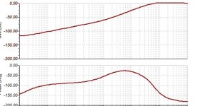
The AD829 is special VFA opamp designed as AD844 with V/I converter and unity gain follower with I out tap. Using it in open loop with 86 ohm resistor and frequency limiter capacitor, I get a differential amp with adjustable gain.
The distortion is not implemented in the model but the output level is 50mv max. The noise very low.
I get down to 0.5uv residual.

The distortion is not implemented in the model but the output level is 50mv max. The noise very low.
I get down to 0.5uv residual.
Attachments
Yes, 20 dB reduction.These are ideal components in a sim. Practical implementation makes getting these figures all but impossible.
If you consistently got 20 dB distortion in a practical amp, I’d say you would have done a good job!
(I must remember not to post from my mobile when in a hurry!)
H
HAYK
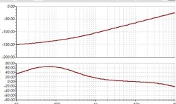
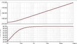
You are perfectly right. If I use Ideal models in sim. I get very easily 3nv residual instead of 500nv with AD829. As you said it is impossible to reach -170db at 1khz but only -107db.These are ideal components in a sim. Practical implementation makes getting these figures all but impossible.
If you consistently got 20 dB distortion in a practical amp, I’d say you would have done a good job!
Notice that the required gain is 1.061 instead of 1.345 in real world , why?
Attachments
H
HAYK
This is a neat approach! I’d like to see a Monte Carlo analysis to get some indication of what’s possible in reality.
- Home
- Amplifiers
- Solid State
- Subtracting error correction