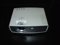
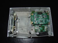
Thought I'll post some pictures of the guts of an LED Projector. Just curious to know whether it had the traditional DLP Colour Wheel or 3 different LED's. Well, I know for sure that it doesn't have a colour wheel so must either have 3 different coloured LED's or 1 bright which changes colour (or can it?). This projector is the Toshiba TDP-FF1A, it is really tiny.
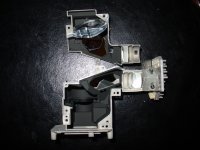
I couldn't take the LED out due to the way it was secured (although I was tempted). The LED seemed to be secured by 4 screws around the light tunnel. I thought that this was the screws for the adjustment of the light tunnel but the LED was not coming out thus I came to the conclusion that it must be secured by of these screws. The screws were thread locked and I did not want to disturb it's position with the fear that I may not be able to get the alignment correct after removal. Anyways, the pictures should give a rough idea of how the whole thing is set up.
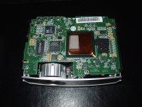
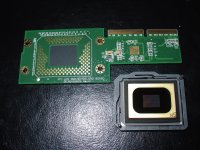
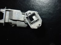
The video controller board is right at the top, the left hand board is the input/output board and it has two power boards on the right hand side. The light engine had two mirrors in a funny angle to each other (where the black tape is and one below/opposite it). The DMD seems like a standard DMD found in any conventional DLP projectors. I didn't go as far as stripping the light engine. This projector gives an alright 60"-70" screen for presentation and about 30"-40" for video. Anything over that gets a bit too dim to be enjoyable. Anyway guys, let's improve these things because I can't see the manufacturers putting too much money on the research and improvements on LED projectors. If it is possible, then it can only improve.
Good luck and all the best with your DIY's. Me myself can't really make the time these days.
I couldn't take the LED out due to the way it was secured (although I was tempted). The LED seemed to be secured by 4 screws around the light tunnel. I thought that this was the screws for the adjustment of the light tunnel but the LED was not coming out thus I came to the conclusion that it must be secured by of these screws. The screws were thread locked and I did not want to disturb it's position with the fear that I may not be able to get the alignment correct after removal. Anyways, the pictures should give a rough idea of how the whole thing is set up.
The video controller board is right at the top, the left hand board is the input/output board and it has two power boards on the right hand side. The light engine had two mirrors in a funny angle to each other (where the black tape is and one below/opposite it). The DMD seems like a standard DMD found in any conventional DLP projectors. I didn't go as far as stripping the light engine. This projector gives an alright 60"-70" screen for presentation and about 30"-40" for video. Anything over that gets a bit too dim to be enjoyable. Anyway guys, let's improve these things because I can't see the manufacturers putting too much money on the research and improvements on LED projectors. If it is possible, then it can only improve.
Good luck and all the best with your DIY's. Me myself can't really make the time these days.
Attachments
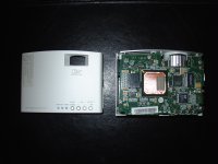

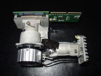
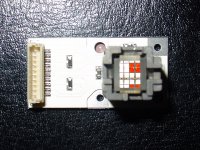
The LED module is the one to the right with the small heatsink. You should be able to remove it with no alignment issues. The holes are not sloted. From the looks of the connector. I would say its 3 colored LED's. Whats the stock brightness? Id really like to see what lenses are used in that tunnel to focus the light.
Ok, guide me through it. I removed the heatsink and there was some rubbery pad between the LED heatsink and the LED module. Even after this, it just wasn't coming off. I tried to prise it off but seemed like it was on breaking point.
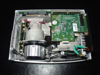
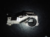
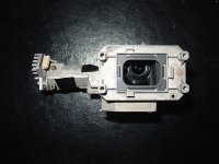
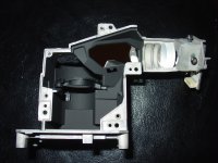
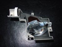
Here's a few more pictures of the Light Engine Overhaul and the LED Lamp. There is a 2x2 grid of which I am assuming the red square is deactivated and the other 3 are the Red, Green and Blue LED. The light tunnel is incorporated into the lamp as you can see from the images and seems to be glued on (the other red and white bit you see is the reflection on the tunnel mirrors. After the lamp, the are 2 convex lens, (first one more than the second). You then have the mirror at a wierd angle, then another non-parallel, again at a wierd angle bending the path. Then you have a big lens prior to the DMD, then the DMD itslef and the projection lens. Seems to be the same setup as a conventional DLP Light Engine. The mirror light tunnel is tiny and stubby by the way (about 12mm). The stock brightness is rated at 35 lumens.
Attachments
Last edited:
Thats very interesting.....The "White" ones are the Green/Blue and the Red is Red. It looks as if theres 7 or 9 LED's based on 1 common ground or 3 seperate grounds. Would be interesting to know the lumen output of the Led's. The rest of the DLP is straight forward. This setup is nice eliminating the rainbow effect.
I would get a Luxeon Rebel 540 Lumen Tri-Star and fire that baby down the tunel and see what you get as far as brightness in Black/White. Try it with a and without the 17* lens they make. The LED would be about $23 1000ma Driver $17 Lens $3. Do some initial tests then maybe look into making a custom array of RGB with the rebels.
Inspect that LED board. You should be able to find what pins control what LED's. You can use 3V to get them going and see what colors are positioned where. I notice 4 SMD resistors so there might only be 4 circuits. I kinda want one now to play with.
I also notice no square mirror tunnel as in most DLP's It just uses the lenses to flood the DMD
The rubber pad is a gasked to keep dust out.
Check out my new thread with my epson!!
Last edited:
- Status
- Not open for further replies.