I have a pair of custom made PP output transformers on EI130 laminated core. The core is a common laminated silicon steel core used in mains transformers. The number of primary is 2 x 1600, the number of secondary turns is 2 x 80. The turns ratio is 20.
Now I wanted to measure the primary inductance, so I connected a 1:1 isolation transformer to the primary and applied 240VAC to it. I measured 12.1VAC on the open secondary, which is about good. The primary current was about 0.8mA. From the XL = 2*PI*f*L I calculated XL = 300kohm, and L = 950H. Is it realistic? I think it is a bit too much 😳 I still have to measure stray capacitances, and where they resonate with the stray inductance.
I also tested it by loading the secondary with a 12V car headlight bulb. Considering the primary and secondary resistive losses all is good. The DCR of the primary is 285ohms, the secondary is 0.5ohm. I had 130mA on the primary and 8.7VAC on the secondary. It seems that is 26W power flowing through the transformer, and the bulb gets some 22.5W after the secondary loss.
Anybody ever measured a commercial OPT? What primary inductance and resistance you get normally? Perhaps my open-circuit measuring method is not correct.
Sounds typical for a push-pull transformer to me. At 240V, 50 Hz, the inductance is much higher than at low levels. But similar to level at 100V, 20 Hz, which will have a similar flux level. I had a big 6.6K output transformer that had inductance in that range (at 20 Hz, 10V!) but its leakage inductance was terrible - 63 mH... good only for a guitar or bass amp. If you have an inductance meter, measure primary with secondary shorted. < 10 mH would indicate good interleaving of pri / sec.
Try the 1uF condenser ub resonance method, the LC circuit is powered by an audio generator with a series resistor of 15-30k and with the frequency determined following the resonance from Thomson's formula is inductiveI have a pair of custom made PP output transformers on EI130 laminated core. The core is a common laminated silicon steel core used in mains transformers. The number of primary is 2 x 1600, the number of secondary turns is 2 x 80. The turns ratio is 20.
Now I wanted to measure the primary inductance, so I connected a 1:1 isolation transformer to the primary and applied 240VAC to it. I measured 12.1VAC on the open secondary, which is about good. The primary current was about 0.8mA. From the XL = 2*PI*f*L I calculated XL = 300kohm, and L = 950H. Is it realistic? I think it is a bit too much 😳 I still have to measure stray capacitances, and where they resonate with the stray inductance.
I also tested it by loading the secondary with a 12V car headlight bulb. Considering the primary and secondary resistive losses all is good. The DCR of the primary is 285ohms, the secondary is 0.5ohm. I had 130mA on the primary and 8.7VAC on the secondary. It seems that is 26W power flowing through the transformer, and the bulb gets some 22.5W after the secondary loss.
Anybody ever measured a commercial OPT? What primary inductance and resistance you get normally? Perhaps my open-circuit measuring method is not correct.
Nothing special: I connected the mains isolation transformer secondary to the primary of the OPT, with the DMM in AC current mode between them. The range was 2mA and I measured 0.79mA/0.85mA (1st trafo/2nd trafo). The secondary was open. 240V divided by 0.8mA gives 300kohm reactance. It is about 950H at 50Hz.On what scale?
Connected "how"?

Here's a PDF from Omicron Labs https://www.omicron-lab.com/fileadm...ling/App_Note_Transformer_modelling_V_2_0.pdf
Hammond uses 27dBu @1kHz for the 1650 series transformers
Hammond uses 27dBu @1kHz for the 1650 series transformers
Link to some testing on early 1950's 'commercial' OPTs. https://www.dalmura.com.au/static/Williamson output transformer measurements.pdf
Thanks.Nothing special:........
Ok, measuring rules.
Looks very high, it would be interesting to introduce some DC, even a few mA, and recheck inductance.
Your measurement is most likely valid - for that particular rms voltage and for that particular frequency and no DC at all.
Inductance rises with excitation - up to a point where saturation sets in.
- you will get smaller numbers with lower rms voltage, try 24V instead of 240V
Inductance drops with frequency.
- you would get smaller numbers with higher frequencies
Inductance drops with DC bias.
- you will get smaller values with additional DC through the windings;
this is difficult to set up though ... I still have to find a simple method to do that.
Using a floating 12V battery and a current setting resistor? My OPT is center tapped push-pull where DC bias currents cancel.Inductance drops with DC bias.
- you will get smaller values with additional DC through the windings;
this is difficult to set up though ... I still have to find a simple method to do that.
In my opinion the best way to test in deep each OT tafo is this:
https://www.diyaudio.com/community/threads/opt-characterization.313957/
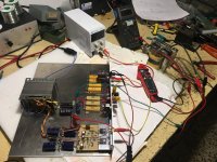
About dc current in OT , in photo th proto of test set ( almost finished), it is complete with a ss amp to drive the OT on secondary
Walter
https://www.diyaudio.com/community/threads/opt-characterization.313957/
About dc current in OT , in photo th proto of test set ( almost finished), it is complete with a ss amp to drive the OT on secondary
Walter
Attachments
The simplest measurement technique I have come across for that is in link: https://www.dalmura.com.au/static/Choke measurement.pdfInductance drops with DC bias.
- you will get smaller values with additional DC through the windings;
this is difficult to set up though ... I still have to find a simple method to do that.
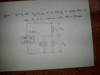
I measured the inductance of the half primary with this method, it gave 16mH. Is it acceptable?Try the 1uF condenser ub resonance method, the LC circuit is powered by an audio generator with a series resistor of 15-30k and with the frequency determined following the resonance from Thomson's formula is inductive
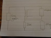
The values of the two inductors found by you cannot be real, from the OT data given by you, the inductance is probably about 30-60H. In addition to the resonance method, an inductor can be measured with the circuit in the photo where the resistor R is adjustable to equalze the two voltage U1 and U2. If the value of the resistor R is measured, the conversion 1H=1Kohm results. Ipracticaly built this device and it works flawlesslyI measured the inductance of the half primary with this method, it gave 16mH. Is it acceptable?
Attachments
Exactly this is the reason why I asked for help. Tomorrow I will do a reverse measurement: attach 12VAC to the secondary and measure the current with open circuit primary. That will give the secondary reactance Xsec, which is 2*PI*f*Lsec. The primary reactance will be n^2 * Xsec. I can take into calculation the resistive part if necessary, but for now I neglect it.That ridiculous low current 0,8mA is not realistic , there must be some kind of error
What meter and range are you using for current measurement?Now I wanted to measure the primary inductance, so I connected a 1:1 isolation transformer to the primary and applied 240VAC to it. ... The primary current was about 0.8mA.
Did you also try and insert a series 'current sense' resistor with the primary winding and measure the voltage across the sense resistor (ie. using 1kohm resistor would generate 0.8Vac across it for 0.8mAac current).
Back in the 1940's they used an AVO 7 to measure OPT primary current was below 0.15mA for applied 5Vac - that was pushing the resolution of the meter at that time, as the needle would hardly have moved on the most sensitive range.
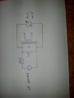
The simplest method of measuring L I've found is wiring the primary of the OPT in series with a resistor, see attached. Connect a sig gen - 20hz to 100khz to them , alter the frequency till you get both meters showing the same AC voltage, then use this formula - R divided by (6.28 x frequency) = L. You might need to change the value of R, but this method works. I've verified it by checking L on an inductance bridge.
You want L primary to be a big as poss, around the 100H ish mark is typical for your average OPT.
Andy.
You want L primary to be a big as poss, around the 100H ish mark is typical for your average OPT.
Andy.
Attachments
- Home
- Amplifiers
- Tubes / Valves
- Strange output transformer measurements - please help explain