Yes i'm rather late, but i hope not to late 😉
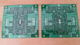
Finally i got hands on a set of Grey Rollins Aleph-X pcbs.
My first plan was to build just the original version with 4 FETs
But i am not shure. Maybe a little bit more power would be usefull 😉
My speakers are all nominal 8Ohms.
But 2 of them have a minimum of about 3,5Ohm
For the 3rd set i have no data.
So treating the Alephs to have more power at low resitances may be not a bad idea.
I found a sheme to wire up FETs in parallel without a PCB. Although being a non electronic, i think i will be able to handle this.
Unfortunately i have some part which i would like to use.
My plan so far:
2 mono Amps
I have 2 toroids each 625VA 2x22V
24 matched FETs IRFP240, so 3 in parallel would be possible, 12 per mono, 24 stereo. I know, to much for the 625VA.
For the power supply i will use a CRC sheme.
I have a set of 60mF condensers.
68mF – 68mF – R – 68mF per rail. Doubble per mono, again doubble for the whole stereo amp.
I am not shure about the resistors, but i have Duncans PSU Designer to play with that.
Beside this i have one Fischer heatsink of about 0,2K/W per mono chanel
Using the Phill AX sheet i could see that lowering the voltage and increasing bias amperage will end in having more power at low resistances
So it looks (at least for me) that i have the wrong FETs and the wrong toroids 😉
Less voltage and IRFP044 might fit better to my ideas.
For the IRFP240 i found a maximum of 25V rail and 1A bias at the Wiki
So what to do?
Maybe one of the more experienced Aleph builders here around has some hints for me.
But please KISS.
I am a none english speaking mechanic 😉
regards Joachim
i hope you did not expec ta simple answer 😉
I would like to say... not yet 😉
All started when i decided to refurbish an older turntable.
Using a 'new' turntable with my old pre?
I was looking for something good but not to expensive.
So i found my way back to the DIY road which i had left about 30 years ago and bought a X-Ono PCB set. Meanwhile that is nearly ready and needs 'only' to be wired up.
Looks like this made me infected by the Pass desease.
Next was a partly mounted P1.7 project. The case and the front plate is still not ready.
So the best for all that would be an Aleph-X, i think 😉
Ok, there is a CD player with balanced output which i had before.
Balanced enough 🙂
regards Joachim
I'm finding that only when you have full balanced system , results are worth trouble
if not , it's cleaner and usually better sounding having fully non- balanced
I was asking just because I had idea to propose decent BA3 amp instead of X , in case of non balanced
anyway - do your math regarding needed rail voltages
regarding number of mosfets - I agree - everything under 3pcs in each quadrant is just waste of time - either make it overkilll (or overkillll or overkilllll , depending of load ) , or don't make it at all
my findings - where differences between 044 and 240 aren't so important - do not go bellow 18Vdc rails (20Vdc even better)
if not , it's cleaner and usually better sounding having fully non- balanced
I was asking just because I had idea to propose decent BA3 amp instead of X , in case of non balanced
anyway - do your math regarding needed rail voltages
regarding number of mosfets - I agree - everything under 3pcs in each quadrant is just waste of time - either make it overkilll (or overkillll or overkilllll , depending of load
) , or don't make it at allmy findings - where differences between 044 and 240 aren't so important - do not go bellow 18Vdc rails (20Vdc even better)
Well, I am starting a low power Aleph X build. Thinking of 1 FET per quadrant, 15V rails, around 4A bias. Why not, Zen Mod, what are the shortcomings?
Currently got a balanced output DAC, a P1.7, which power Aleph 5's via balanced inputs. Now want to try full balanced all the way
Currently got a balanced output DAC, a P1.7, which power Aleph 5's via balanced inputs. Now want to try full balanced all the way
I'm finding that only when you have full balanced system , results are worth trouble
if not , it's cleaner and usually better sounding having fully non- balanced............
+1! 🙂
Well, I am starting a low power Aleph X build. Thinking of 1 FET per quadrant, 15V rails, around 4A bias. Why not, Zen Mod, what are the shortcomings?
Currently got a balanced output DAC, a P1.7, which power Aleph 5's via balanced inputs. Now want to try full balanced all the way
at least use IRFP150N .... that thingie is replacing two pcs of IRFP240
when speaking of numbers ..... we are speaking of xconductance/Rout ..... read - both current capacity and damping factor
regarding number of mosfets - I agree - everything under 3pcs in each quadrant is just waste of time - either make it overkilll (or overkillll or overkilllll , depending of load
hmmmm.... that is this kind of overkill i would like to avoid.
Overkill may end in over*s*kill
On the other hand, if i have the 3 FETs per quadrant why not using them.
Wiring 2 will be the same as wiring 3.
The worst thing which can happen ist that i will have to add a second heatspread or/and my toroids will have not enough power.
Just another question. I somewhere read that Q5 and Q/ should have a heatspread to. I have an aluminium U-profile out of whcih i can cut a small heat spread.
Two of them glued back to back should fit on the footprint on the PCB.
Any advice how much K/W the heat spreads should have?
What about Q6. Should it also be cooled?
Somewhere i read that it would be better to mount Q6 together with the FETs on the big heat spread.
Beside this i found a servo circuit to minimize DC output. But i think this will be really an overkill for my limited skills 😉
regards Joachim1
uupsss... somehow i thought everybody is using the same PCBs or shematics 🙂
That's what i am using (see attached files)
Q5, Q7 and Q6a are IRF9610
Playing around with the SPU Designer another question appeared.
How much load can a i put on a 5W resistor?
For me it looks like the laod on those resistors in a C-R-C power supply are far away from those Watt values printed on them.
At the moment i have about 2,5V and 3A at the resistor. About 7,5W
There is room for 5 parallel resistors on my PCB
Using 5W resistors they will together resist 25W.
Would this be ok?
Maybe i should look for a data sheet 🙂
Maybe there are some informations about the allowed wattage compared to the temperature.
Or is there any rule of thump?
regards Joachim
Attachments
according to that schmtc , it is wise to clamp Q5 and Q7 together with screw , as it is obviously intended on pcb - just put isolating pad between them - silpad is good enough for that
that should improve offset behavior , in temp. domain , these two mosfets being in input LTP
regarding R in CRC - usually there is 0R1 for R
if you're using 0R1 you can freely put through such current to achieve 2.5W of dissipation (100% deration factor ..... or 50% , depends how you look at it )
so , for 0R1 that would be (by P=I^2 x R) 5A
if you need more power for R cell , just put few resistors in parallel - say two of 0R22
now you have formula , calc by your self
according to that schmtc , it is wise to clamp Q5 and Q7 together
yes, read about this.
My idea was to add a heat sink between the two.
now you have formula , calc by your self
although i am a mechanic i can handle such (simple) calculations 😉
My question was more how much load i can add on a resistor which is marked with 5W
Just after i have asked this i had an idea.
Why not simply having a look in the datasheet 🙂
I found what i am looking for.
My resistors will resist 5W up to about 70 degrees Celsius ambient temperature.
Up to 200 deg this will drop to 35%
So the 5 pieces 5W each in parallel will be good for much more load than i have.
regards Joachim
Joachim,
When soldering the resistors to the PCB make sure to rise them about 3 mm above the board to allow for air circulation and effective cooling. Also, if you decide to use 5 resistor per rail, I suggest the 0.56 ohms value for each, or any combination that keeps the association around 0.11 ohms.
When soldering the resistors to the PCB make sure to rise them about 3 mm above the board to allow for air circulation and effective cooling. Also, if you decide to use 5 resistor per rail, I suggest the 0.56 ohms value for each, or any combination that keeps the association around 0.11 ohms.
i have a list with collected tips and hints.
There i found a notice from someone who had troubble with DC ofset.
Mounting Q5 and Q7 on a heatspreader solved the problem.
Maybe *mounting them together* (isolated) was the solution, not the heatspreader.
Cant find the article at the moment.....
What about Q6a?
Leaving on the PCB or mounting it isolated on the big heatspreader between the FETs
I also have this on my little list. Doing this should minimize DC ofset while warming up.
I should also search for the article where i have read this 😉
My resistors are a bit longer than the footprint on the PCB. Therefore i have to lift them up anyway 🙂
As there is no copper layer under the resistors i could drill some small holes for better cooling.
The PCBs are also prepared for C-L-C, so i could use those thick aluminium resistors with 50 or 100Wmounted beside the power supply unit on the heatspread and wiring them up.
BTW thanks a lot for the help 'designing' my Alephs 🙄
regards Joachim
beg your pardon, i have been 'out of order' for a few days.
Meanwhile i have found the article. I think it's well know here.
Aleph-X 100w Amplifier Construction Notes
Mounting the device on the big heatsink was not for cooling but to keep it at the same temperature as the FETs. This should improve the behavior while heating up
I think i will mount it without the external wiring first.
Maybe i will try it later on.
One extra bore an taping will be done easy.
Beside this i will give the 3 FET solution a chance when i have collected the bits an pieces i did not have yet.
Maybe this will last some..... years 😉
Thanks a lot for your support, Joachim
So I am progressing with my Aleph X build. Bought 20 pieces of IRFP150N, thanks to Zen Mod advice. Got 8 pieces match Vgs to 0.01V at 1A and at 2.25A, but not enough matches to have 2 device per quad, so still keeping it simple
I have some questions now:
1. I plan to mount source and gate resistors on the PCB, which will be on the back panel of each monoblock. So I will run wires to FETs, 15-25cm length. I got me thinking about bunch of parallel wires at high currents - should I be worroed about interference? Maybe use shielded cables and earth shields at PCB end?
I know standard output boards would also have parallel traces, but still not completely at ease here
2. JFET inputs. I have matched Toshiba J74's that I want to try to swap in (have PCB pins installed). Do I short gate resistors and that's all?
Thanks
1.answer to your question lies in most fresh picture of most fresh Papa's creation - XA25
look in thread and find link to pdf in few last posts
gate resistors - solder them ditto on gate pin , use heatshrink to secure them both to thin wire and mosfet gate pin
that way things will be much less critical
2. you mean some special shorting procedure while pulling them out/installing new ones ? naah ........ just take care that you didn't overly full of static electricity ...
1.answer to your question lies in most fresh picture of most fresh Papa's creation - XA25
I see non shielded non parallel wiring. OK..
- Status
- Not open for further replies.
- Home
- Amplifiers
- Pass Labs
- still any Aleph-X builders here?