Hello everybody.
I opened this thread for illustrative purposes only.
I managed to do something that I want to share with this community.
I have a Stetsom 3k3es amplifier that has suffered significant damage both in power and audio, also damaging the primary IC (PIC16xxxx).
Unfortunately, it was impossible to find this IC without making too much effort (the manufacturer was not very helpful).
Since without that component, the amplifier would never have worked, so I should have thrown it in the trash, I decided to experiment.
I generated everything I needed, everything the IC does.
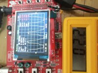
I made a separate external power supply to operate the power supply and an external oscillator to generate the carrier for the audio.
Now the protection systems do not work, but with a little effort they can be realized without problems.
I realize that it is unnecessarily complicated and that a new IC would have solved all the problems in one fell swoop, but in extreme evils, extreme remedies, it was a fantastic experiment that I didn't think I would complete and I learned many new things about these Brazilian amplifiers.
thanks to those who want to follow me.
YouTube
I opened this thread for illustrative purposes only.
I managed to do something that I want to share with this community.
I have a Stetsom 3k3es amplifier that has suffered significant damage both in power and audio, also damaging the primary IC (PIC16xxxx).
Unfortunately, it was impossible to find this IC without making too much effort (the manufacturer was not very helpful).
Since without that component, the amplifier would never have worked, so I should have thrown it in the trash, I decided to experiment.
I generated everything I needed, everything the IC does.
I made a separate external power supply to operate the power supply and an external oscillator to generate the carrier for the audio.
Now the protection systems do not work, but with a little effort they can be realized without problems.
I realize that it is unnecessarily complicated and that a new IC would have solved all the problems in one fell swoop, but in extreme evils, extreme remedies, it was a fantastic experiment that I didn't think I would complete and I learned many new things about these Brazilian amplifiers.
thanks to those who want to follow me.
YouTube
Did you try to get it from one of the other brazillain amp clone 'manufacturers'? Some of them will sell you the PIC.
I know that soundigital produces some models for ground zero, deaf bonce and other improvised houses, but I have never seen the STETSOM design in amplifiers of other houses, although the operating principle remains the same, the PIC of "similar" amps "may have a different program code.Did you try to get it from one of the other brazillain amp clone 'manufacturers'? Some of them will sell you the PIC.
Also, as this amp didn't matter to me, if I could fix it with the original PIC, well, otherwise, I learned new things by doing this experiment.
Why you don't try to make another pwm generator for this amp?
Tomorrow i'll test my mcu pwm generator
As you know how that work,you can programming another ic easily
Tomorrow i'll test my mcu pwm generator
As you know how that work,you can programming another ic easily
Are you referring to a second generator for the audio stage?
The PIC generates a carrier that's converted to a triangle waveform for audio PWM.
The PIC generates a carrier that's converted to a triangle waveform for audio PWM.
I just use mcu for making smps and i tested that
The result was good
I'll make a simple board soon
I just have a problem about gate driver
As you know when mcu work with 5volt and that pwm have 48% dtc,output is about 2.2volt.(like result of my test)
I try to use tc4427 as push pull gate driver but it need 2.4v(min input signal's voltage) to work
Now i don't know it can work with 2.2Vac or not
You know?
My second project is mcu class d modulator 🙂
Drive a high speed open collector comparator to boost the drive voltage.
The amplitude of the signal at 48% isn't 2.2v. If it reads 2.2 with a multimeter, it's likely very near 5v in amplitude.
Rockford drives their TC4420 drivers with a 3v signal (ground to 3v).
The internal diagrams are sometimes misleading but it appears that the inputs are simply FETs. If you can reach the threshold for that FET (5v amplitude will), the driver will switch.
Please don't post in a repair thread that was started by someone else unless you are trying to help them.
Start a new thread if you need help with a repair of your own.
Start a new thread if you need help with a repair of your own.
Perry I've started 2 threads asking if anyone can help identify 2 ic's on a stetsom 5k with no reply what harm is there in asking someone who has one that they are busy with to help identify the missing components?
Contaminating threads with something other than what the OP was makes the forum much less useful. Clean threads make this forum one of the best. It could be that no one has the answer you need.
- Home
- General Interest
- Car Audio
- Stetsom Amps - Hacked PIC - Experiment