Hi!
I had an old Srm-T1 lying around.
It sounded ok on my Stax 407 Pro headphones but I thought that maybe some recapping and adjustments was needed.
Originally there was 4*100uF Caps in the power supply. I changed to 4*680uF and it was a nice upgrade.
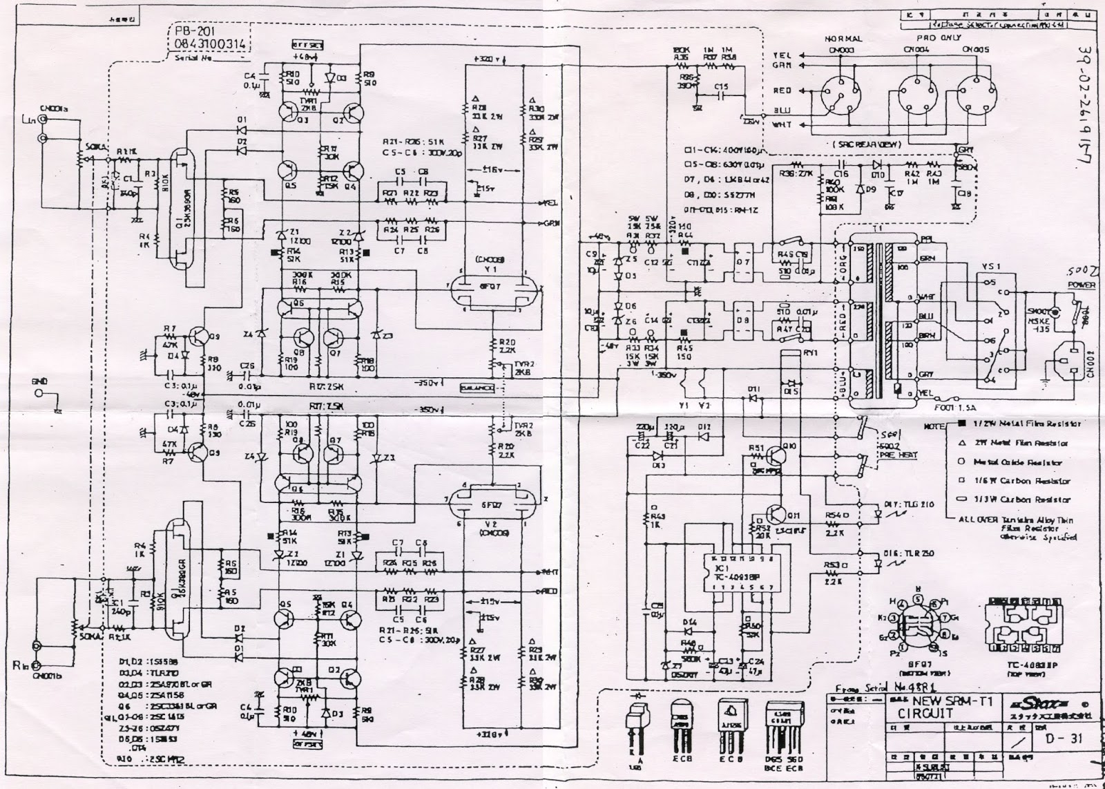
Then I found that changing the anode resistors (66kOhm) to a CCS was a good thing and here is the schematic found on "head-fi" and muffinhead post:

It works well on low current 1mA, but It went into oscillation above 4mA. Any ideas how to make it more stable?
EDIT: The top transistor is 10M90S.
I had an old Srm-T1 lying around.
It sounded ok on my Stax 407 Pro headphones but I thought that maybe some recapping and adjustments was needed.
Originally there was 4*100uF Caps in the power supply. I changed to 4*680uF and it was a nice upgrade.
Then I found that changing the anode resistors (66kOhm) to a CCS was a good thing and here is the schematic found on "head-fi" and muffinhead post:
It works well on low current 1mA, but It went into oscillation above 4mA. Any ideas how to make it more stable?
EDIT: The top transistor is 10M90S.
Last edited:
I made the leads shorter between 10M90S and DN2540 (thanks JimL11 on head-fi), decoupled the +powerline input and now it works like a sharm!
For higher voltages such in tube amplifiers this currrent source is really good!
It can handle up to 100mA.
For higher voltages such in tube amplifiers this currrent source is really good!
It can handle up to 100mA.
when i added some 10uf polypropylene caps to supply, it improved treble.
i already i had 1000uf/400 there..
i already i had 1000uf/400 there..
Went in to your site Peter... interesting.
What do you think about having SRM-T1 with total 4*CCS (like the one on the schematic, having > 100Meg ohm virtual impedance (getting lower at high frequencies), and then a 150H choke in series efter the CCS, and then the anode.
I believe the voltage swing will be higher due to the back EMF from the choke (as you know) and also the increased impedace at higher frequenzies in the treble, stabilizing the current noise?
replacing anode resistors with ccs? everything is possible.
i see small issue, adjustment of tube cathode trimers , vs ccs currents.
it may fight first, but when finished adjustment, it would be better than anode resistors.
for safety reason, ccs mosfets should be rated 1000v.
but still, i have mixed feelings because i hate global fb. and here it is unavoidable, because of dc point. otherwise magic smoke comes out.
but i am more gyrator guy, it is less setup pain for me.
(last two pictures specifically on my mind ) http://peteslab.blogspot.com/2015/11/stax-2a3-se-amplifier.html
Last edited:
hpeter After getting it stable its really good as it is. In the schematics it´s noted that the anode voltage at steady state should be within +/- 15volts. I have stored it in cold temperature and had it running for long time and it stays within +/- 4 Volts.
Whatabout adding a 150H shoke after the CCS?.. I have not simulated it yet... but you should get "back emk" and higher voltage swing right?
Whatabout adding a 150H shoke after the CCS?.. I have not simulated it yet... but you should get "back emk" and higher voltage swing right?
- Status
- Not open for further replies.
- Home
- Amplifiers
- Headphone Systems
- STAX amplifier with CCS