I've been looking at planning the star grounding for my tube amp project. Going through what I have read is that the star ground reference point should also be connected to the chassis. My plan was to build the chassis out of wood, though, will that cause an issue (e.g. hum) ?
Hi all,
I've seen/listened to many stone silent amps built in wooden chassis, so I would not be too concerned.
Of course, the residual noise depends on the way you will be building the amp.
I would separate the signals ground and the power supply ground and I would get both of them to the star grounding.
If you want to be very rigorous,
1. get EACH signal ground from each stage of each channel individually to a signals star ground.
2. get the ground of the first cap in the power supply to a power supply star ground
3. without connecting the first cap ground to the second cap ground, get the rest of the power supply ground to the same power supply star ground.
4. get the inputs ground and the volume pot chassis to the signals star ground
5. if you ground the output, get it to the signals star ground.
6. get the power supply star ground and the signals star ground to a unique star ground.
7. Using a 100R resistor bundled with a X2 film capacitor, get the unique star ground to the Earth.
8. I personally use shielded cables for inputs and for grids in the first stage (if the distance from inputs to grids is not too short). Interstage cap is always cut short. I don't rely on the fact there is no audible noise, using shielded cable leads in my opinion to a better SNR overall.
9. I am using bifilar winded heaters power transformers and I am grounding the center tap. Being bifilar winded, you'll always be sure that both windings (i.e. 3.15 + 3.15 V) have sensibly equal DCR. This way there will be a minimum of noise using AC powered heaters. It works with DHT's very well too and it is a cheap solution.
Sorry for being so long and possibly off-topic, I guess I have written logorrhea.
Last edited:
I'd want to put some metal shielding inside the wood cabinet. A thin steel or aluminum sheet inside each panel will do, as long as they're all connected to the circuit's ground.
MUMetal shielding
If so, pcx sells a MUMetal shielding: CONNEX-76151
And they have 20% discount right now
I'd want to put some metal shielding inside the wood cabinet. A thin steel or aluminum sheet inside each panel will do, as long as they're all connected to the circuit's ground.
If so, pcx sells a MUMetal shielding: CONNEX-76151
And they have 20% discount right now
I'd want to put some metal shielding inside the wood cabinet. A thin steel or aluminum sheet inside each panel will do, as long as they're all connected to the circuit's ground.
Why would you?
Either make a complete RFI shield (and shield the tubes as well) or leave it. Metal box amplifiers can be noisier than wooden box amplifiers, depending on the circuit and the parts used.
Amplifier performance and safety are two separate issues.
Connecting the Protective Earth (PE) permanently to Chassis and connecting all exposed conductive parts to the protected Chassis are Safety issues. Deal with them completely and independently of amplifier performance.
Once the Safety issue and all it's complications are clear and you have a plan to implement, then forget about them while designing and assembling the equipment.
THEN add back in the Safety, fully.
Don't use mumetal for screening. It is expensive, unnecessary for electric field screening (any metal will do) and largely ineffective for magnetic field screening unless used by someone who knows exactly what they are doing.saptemari said:If so, pcx sells a MUMetal shielding: CONNEX-76151
My guess is that the OP is confusing two quite separate issues with the usual metal chassis/box. One is safety: the metal provides both a physical barrier and an electrical barrier to keep users away from high voltages. Wood provides an adequate physical barrier; you just have to ensure that any external metalwork is grounded. The other issue is circuit grounding, which if done properly will be unaffected as the metal chassis should never be used for signal ground in audio equipment (unles you like hum).
Don't follow grounding recipes; even good ones, and certainly not bad ones. Instead, think about where the currents flow (always in loops), remember that there is no such thing as 'a voltage' (voltage is always between two points), and remember that electric fields couple via surface area and magnetic fields couple via loop area.
and all the joints are electrically continuous.I'd want to put some metal shielding inside the wood cabinet. A thin steel or aluminum sheet inside each panel will do, as long as they're all connected to the circuit's ground.
The length of the slot/gap determines the frequencies that pass through the slot.
thanks guys for the detailed answers already. I love this forum 🙂 On a very simple level, though, the following issue remains:
All ground cables are connected at a terminal strip ("star ground"). Does that conclude it when using a wooden box or should I add another cable from the terminal strip (star connect) and wire it somewhere and if so, where ? Drill a hole in the back and run a cable out the box and ground it somewhere ourside ?
All ground cables are connected at a terminal strip ("star ground"). Does that conclude it when using a wooden box or should I add another cable from the terminal strip (star connect) and wire it somewhere and if so, where ? Drill a hole in the back and run a cable out the box and ground it somewhere ourside ?
What do you mean by "all"? Does that include a safety ground connection?weber30 said:All ground cables are connected at a terminal strip ("star ground").
No. That could be dangerous, as you may be introducing two different electrical 'grounds' into the same room.Does that conclude it when using a wooden box or should I add another cable from the terminal strip (star connect) and wire it somewhere and if so, where ? Drill a hole in the back and run a cable out the box and ground it somewhere ourside ?
'Ground' is not some magic sink for all unwanted hum/noises/inteference. All you need to do is establish one point from which all signal voltages take their reference.
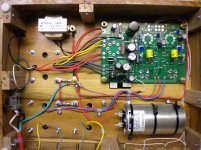
You have lots of single wire connections.Here is my wooden chassis. Since the photos I changed the input wires to coax cable...dead silent.
Every input and every output and the power supply are two wire connections to the outside world.
They should all be two wire connections with the two wires close coupled along their whole route. Even better if the two wires are a twisted pair along their whole route.
This allows for better rejection of interference.
Might be quite important with an unscreened Chassis.
Try placing any "wireless" radio equipment on top of or next to your box and hear what comes out of the speaker, when the door bell rings or the mobile phone communicates or the fire alarm/smoke detector triggers or the wireless landline rings or the WiFi communicates or the ......
Andrew you are correct. This was one of my first builds.... I have read and tried to understand things as time has gone by. I have taken your advice on close coupling when laying out wiring for projects. Also your advice on not fusing the neutral line.... In this case simply using coax for the signal wire cleaned things up.
E
E
It looks tidy. I use similar grounding technique for prototype builds - those eye terminals make ground connections easy - make sure these and the star point is most firmly attached.. More "permanent" builds get a grounding bus in my builds.
Andrew's advice is spot on. I might have said it this way: for every longer AC connection make sure you use twisted pair. This includes connections to the OPT. It is of course not reasonable to do this for connections between valves.
From your photo, it looked like your input grounds are all connected together. When you changed it to coaxal cable, I suspect the were then separated. So the same improvement might have been achieved by simply using twisted pair. Of course if the coax is in there and works then its best to keep it. 🙂
Ian
Last edited:
The main thing to remember is,
Any exposed metalwork that could become live under fault conditions must be earthed.
This is to ensure the protective device ie fuse will operate and prevent a dangerous rise in potential.
So things like transformers etc. must be earthed.
Also any capacitors that are exposed with metal cases..if you cant earth it then don't expose it..🙂
I like using wood however I run a protective cable to ALL metalwork and take it back to the mains Earth including valve bases.
You can use plain PCB to create a ground potential and shield under the wood which will earth most of the things mounted on the top..
You can also use foils glued inside the box and earth that..depends how far you want to go..
You could just use ring tags under the chassis connected to a mounting pin/bolt for the things on the top..and check you have a good earth with a multi meter.
Then run a single Earth wire through each of them and connect the wire to the incoming Earth..
If you use a piece of solid core you can use one continuous wire passed through sleeving and through the ring tags so if a connection comes adrift it doesn't break the Earth connection to the other parts. So you would have one Earth bus bar run to all the components just to one mounting point do this as soon as you mount the parts on the top then you can just connect everything else as normal.<<<Easy and neat!
So mount all your parts on the wooden case and just install a ring tag on one connection of each item..run your protective Earth and solder in place.
Remember to take it to the controls (volume etc) so anything you can touch is at Earth potential and if something comes lose in the chassis and touched the back of the volume pot it will blow a fuse and can't become live. Takes an extra 20 mins to do!
The star ground is treated as a separate issue and the buss ground is left alone.. ie create the star ground to a different point and then run an Earth from that to the incoming Earth supply.. so you would have two connections on the Earth..then if you want to lift (not disconnect) the star ground you have the choice..
Regards
M. Gregg
Last edited:
If you use foil inside a chassis,
Don't use it as the bus Earth its just grounded shielding..ie not current carrying..
If you use PCB it can be used as bus ground..take a wire from it to supply Earth.
I try to take into account physical strength of the Earth connections..as long as I can work with them not to stiff..
(Big enough cross section to carry fault current without failing)..so the fuse clears the fault..ADS
You can make hard wired circuit boards and use the copper on the PCB as shielding and not use it as a ground plain..e.g.
Then you could mount the PCB's under the wood and use wood screws that don't come all the way through to top plate..
Regards
M. Gregg
Attachments
Last edited:
If you were serious enough you could mount the hard wired PCBs onto rubber shock absorbers and mount that onto another plain PCB and mount that onto the wood top plate..use aluminium foil glued as shielding inside the box and Earthed..with the circuit boards spaced away by about 5mm..years ago some TVs had foil shielding inside wooden cases it not a new idea..🙂
You could use ground planes for each board and bring them all back to a star ground then take that to the suppy Earth..
I could drone on..however you get the idea..
With the hard wired circuit boards you don't even get the valve base screws through the chassis..its all held in place with wood screws or blocks glued to the top plate..
Regards
M. Gregg
Last edited:
The secondary rule "all exposed conductive parts should be connected to the (protected Chassis)" becomes the main rule where no external Chassis is being used.
It's a lot of extra safety connections and I would be surprised if it only took 20minutes to couple them all back to the PE connection/wire.
It's a lot of extra safety connections and I would be surprised if it only took 20minutes to couple them all back to the PE connection/wire.
The secondary rule "all exposed conductive parts should be connected to the (protected Chassis)" becomes the main rule where no external Chassis is being used.
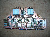
This is what I was wanting to show with my photo.
- Status
- Not open for further replies.
- Home
- Amplifiers
- Tubes / Valves
- Star grounding - wooden box