All,
I just completed a magnetic phono preamplifier project. It is a relatively simple unit that uses all 6C45P Soviet designed tubes.
Photos of the unit are below.


Schematics along with AC (in green) and DC (in red) node voltages are recorded below. This data was taken 20 minutes after unit was powered with a BK Precision 5491B 5000 count multimeter. Mains AC measurements were taken with respect to neutral. Heater AC measurements were taken with respect to the GRN and BRN wires. High-voltage AC measurements were taken across the YEL and WHT wires. All DC measurements were taken with respect to GND.


In summary:
1. All audio performance data was taken with a QA403 Audio Analyzer. The yellow line is the left channel, the red is the right. Photos of the test setup are below.


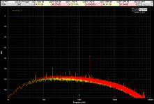
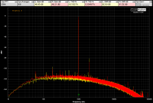
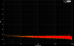
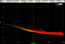
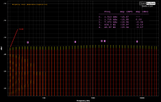
2. The unit was designed to take a -48dBV signal, off a moving magnet pickup, and amplify it to around 0dBV, at 1KhZ, with a 22k ohm resistive load on the output. See image 4 for a test tone on an unloaded output and image 5 for a loaded output.
3. THD, at 1kHz, ranges from 0.004% to 0.01% with no load, and 0.01% to 0.02%, with the 22k ohm load.
4. Unweighted, the signal to noise ratio ranges from 68dB to 71dB. With A-weighting, it is between 81dB and 83dB. Note that the testing was not done with great quality RCA cables, as I have none on hand. This explains the 60Hz spikes and harmonics present in the data. With better interconnects, I expect the signal to noise ratio to improve, along with the THD.
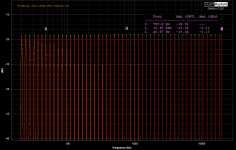
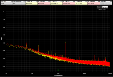
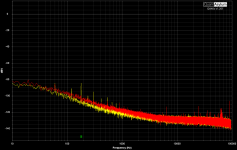
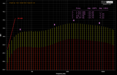
5. When RIAA weighting is applied to test tones across the audio band, there is 0.2dBV or less deviation between the tones. See picture 7.
Questions:
1. What do you all think of this unit, its construction, and the test results?
2. I only tested the unit. I have not yet listened to it. How do you think it will sound?
3. What RCA cables do you suggest I use? The ones I happen on seemingly pick up more hum that they should.
Thanks,
The TorroidDoughnut
I just completed a magnetic phono preamplifier project. It is a relatively simple unit that uses all 6C45P Soviet designed tubes.
Photos of the unit are below.
Schematics along with AC (in green) and DC (in red) node voltages are recorded below. This data was taken 20 minutes after unit was powered with a BK Precision 5491B 5000 count multimeter. Mains AC measurements were taken with respect to neutral. Heater AC measurements were taken with respect to the GRN and BRN wires. High-voltage AC measurements were taken across the YEL and WHT wires. All DC measurements were taken with respect to GND.
In summary:
1. All audio performance data was taken with a QA403 Audio Analyzer. The yellow line is the left channel, the red is the right. Photos of the test setup are below.
2. The unit was designed to take a -48dBV signal, off a moving magnet pickup, and amplify it to around 0dBV, at 1KhZ, with a 22k ohm resistive load on the output. See image 4 for a test tone on an unloaded output and image 5 for a loaded output.
3. THD, at 1kHz, ranges from 0.004% to 0.01% with no load, and 0.01% to 0.02%, with the 22k ohm load.
4. Unweighted, the signal to noise ratio ranges from 68dB to 71dB. With A-weighting, it is between 81dB and 83dB. Note that the testing was not done with great quality RCA cables, as I have none on hand. This explains the 60Hz spikes and harmonics present in the data. With better interconnects, I expect the signal to noise ratio to improve, along with the THD.
5. When RIAA weighting is applied to test tones across the audio band, there is 0.2dBV or less deviation between the tones. See picture 7.
Questions:
1. What do you all think of this unit, its construction, and the test results?
2. I only tested the unit. I have not yet listened to it. How do you think it will sound?
3. What RCA cables do you suggest I use? The ones I happen on seemingly pick up more hum that they should.
Thanks,
The TorroidDoughnut
Attachments
-
 7. Unit On - -48dB In 22k Load RIAA Weighted.png86.7 KB · Views: 97
 -
 6. Unit On - -48dB In 22k Load A Weighted - Copy.png122.4 KB · Views: 86
 -
 5. Unit On - -48dB In No Load A Weighted.png119.1 KB · Views: 80
 -
 5. Unit On - -48dB In Load 22k.png121.8 KB · Views: 75
 -
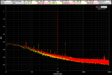 4. Unit On - -48dB In No Load.png123.9 KB · Views: 79
 -
 1. No Power.png97.4 KB · Views: 83
 -
 2. Unit On - Inputs Not Shorted.png102.3 KB · Views: 87
 -
 3. Unit On - Inputs Shorted.png105.2 KB · Views: 92

Hi
Did you measure it for RIAA curve accuracy? Other than that it looks like a very tidy build. Congratulations!
Questions
1. What do you all think of this unit, its construction, and the test results? - Your test results look like I would expect. Wait until you listen to it though, because your testing won't show you if you pick up RF signal or if your 6C45P's oscillations (which they are famous for).
2. I only tested the unit. I have not yet listened to it. How do you think it will sound? Well, since the output impedance is not very low, it won't be able to drive long cables, cables with much capacitance or stages with low input impedance so well. The effect might be quite audible depending on how you plan to use this amplifier.
3. What RCA cables do you suggest I use? From looking at your pictures, the test cables you are using appear to be fine quality. For MM phono, I try to use phono connections with the lowest capacitance possible. Most phono cables are at least 100pF when you use RCA connectors. When connecting it to the following stage, make the cables low capacitance and as short as possible for the reasons I described above.
Additional comments: These days all my phono amps go in enclosed metal boxes. And I use every trick possible to avoid RF interference. Cell phone signal interference is everywhere these days. Tip: to solve the high output impedance problem, I would suggest a mosfet follower, loaded by a constant current sink.
Question: Are you using blue LED's for cathode bias? It looks like this in your picture... The bias point is probably much higher than it needs to be if you are using blue LED's. It's just my opinion, but I would not use LED on the input valve/tube since the input signal is quite low, and any LED noise will get amplified from this point onwards. I would use an un-bypassed resistor instead. That said, the 6C45 only has an amplification factor of 50 or so, so an un-bypassed cathode resistor on the first stage would reduce the total gain. This might be undesirable.
Looking at the 6C45 plate curves, if you are running 125V on the plate with a cascoded CCS, and if you are using blue LED's (with a forward voltage of at least 2.5V) it looks like you are right in the knees of the plate curves. Again, the LED's look blue in the your picture. Maybe it's a photographic artifact and they are actually infra-red?
Last edited:
Hi soulmerchant,
The LEDs are not blue, they are IR. The schematic voltage readings show a drop of around 1.2V at each cathode with respect to GND. Did you look at it? A blue LED, like you said, will drop around 2.5V. I agree 2.5V is an inappropriate DC biasing point for a 6C45P.
Correct me if I am wrong, but IR emitters are not particularly noisy. I chose them for the bias point, and the need to not include a resistor bypassed with a cap, which adds a low-frequency time constant. I'll admit, I did not research the topic of LED noise figures, and what those would be vs. that of a resistor.
As for the RIAA response, I did include this in my data. Did you not see it? It is picture 7.
I did test the unit unloaded vs. it being connected to a 22k ohm load (see pictures 4 and 5). The load was connected with a 1 meter RCA cable. I observed a 0.6dB loss of signal (across the whole audio band) along with a 0.015% rise (worst case) in THD at 1kHz. There was no observable high-frequency roll off, which I would expect to see with cable capacitance. The RIAA data was taken with the load connected, and there was less than 0.2dB of deviation.
The only evidence, from my testing, that correlates to output impedance, is signal loss and THD. As per RCA cables, you mentioned length/capacitance, but did not give any numbers. So for a cable, what is considered long? What capacitance is considered high for an RCA cable? And what do you consider low for an input impedance of a following stage?
Finally, is there any more data you or anyone else would like me to post?
Thanks
Very nice. But I'll be amazed if those 6C45 aren't oscillating at tens of MHz. Hopefully, a grid stopper in lieu of your jumper will fix that if necessary. A rather more fundamental issue is that turntables have their arm on the right hand side and motor on the left. For minimum hum induced by the motor, we put the RIAA stage to the right of the turntable. But that puts your mains transformer near the cartridge. It would be better to mirror your RIAA stage and put the transformer on the right...
First off, let me congratulate you on a very attractive and tidy build. I like the look of it, very much.
Re: LED bias of the input stage -- I think noise from the IR LED in the cathode would show up as hiss. If that's a problem, you could bypass the IR LED with a 220uF 16V capacitor to reduce noise. or you might want to switch to a bypassed cathode load resistor. Or, you might be able to get away with leaving a cathode bias resistor unbypassed, but that would reduce the PSRR of that stage. Of course, the cascode CCS in the input stage plate circuit gives it really good PSRR, so maybe you'd get away with it. There is no single 'best' answer here, I think.
Re: LED bias of the input stage -- I think noise from the IR LED in the cathode would show up as hiss. If that's a problem, you could bypass the IR LED with a 220uF 16V capacitor to reduce noise. or you might want to switch to a bypassed cathode load resistor. Or, you might be able to get away with leaving a cathode bias resistor unbypassed, but that would reduce the PSRR of that stage. Of course, the cascode CCS in the input stage plate circuit gives it really good PSRR, so maybe you'd get away with it. There is no single 'best' answer here, I think.
for a cable, what is considered long? What capacitance is considered high for an RCA cable? And what do you consider low for an input impedance of a following stage?
Not that anybody asked me, but...
Long RCA cable might be 10 feet/3 meters.
If the RCA cable has capacitance of 100pF/foot, that 10 foot cable could have 1nF of capacitance. That would be high in my book.
Many of today's class D amps have input impedance of 10k ohms. One headphone amp I have has a 5k ohm volume control (<5k ohm Zin). That would be low.
You all raise good points about the 6C45P tubes going into whistle mode (parasitic oscillations). That was problem I took into account in designing the unit. It did not arise, without grid stopper resistors (grid stoppers add noise), so I did not report my findings on it.
To ensure the unit was not whistling, I checked the output with my oscilloscope at idle, with the -48dB 1kHz signal, and while powering up and powering down for RF noise. I found no evidence.
I suspect oscillations have more to do with inductive return paths at RF frequencies, rather than the tubes themselves. The boards in the phono stage have ground planes on the bottom side, which may explain why I am not seeing any whistling.
To further test performance, I attached 3 meter cables and retook the 1kHz tone data. Pictures 1 and 2 show 1kHz tone performance with 22k ohm and 10k ohm loads respectively. As expected, the signal to noise ratio dropped by around 3dB (with respect to my original data) due to hum pickup of the long cable. With a 10k ohm load, there was around 0.5dB more signal loss, and a further increase of THD, with respect to the 22k ohm load.
Just so everyone knows, as far as the RIAA data is concerned, I was not particularly thorough in taking it, so I attached better data. Pictures 3 and 4 show RIAA performance with the 22k and 10k ohm loads. There is 0.33dB of deviation with the 22k ohm load, and 0.62dB with the 10k ohm load. This is because C18 and C28 make a high-pass filter with the loads. Increasing the values of C18 and C28, along with R28 and R38 will improve the deviation. The only drawback will be more low-frequency signal when the unit is not loaded or lightly loaded. As far as high-frequency roll off is concerned, there is still no evidence of it.
Just so everyone knows, as far as the RIAA data is concerned, I was not particularly thorough in taking it, so I attached better data. Pictures 3 and 4 show RIAA performance with the 22k and 10k ohm loads. There is 0.33dB of deviation with the 22k ohm load, and 0.62dB with the 10k ohm load. This is because C18 and C28 make a high-pass filter with the loads. Increasing the values of C18 and C28, along with R28 and R38 will improve the deviation. The only drawback will be more low-frequency signal when the unit is not loaded or lightly loaded. As far as high-frequency roll off is concerned, there is still no evidence of it.
Attachments

I don't understand why you don't try it out. As it is I expect the following problems:
1. Audible noise from initial LED biased triode (as noted already by me and others)
2. 6C45P's oscillations which will possibly even be audible (as noted already by me and others)
3. Lack of drive for longer cables and/or connection to following stages with lower input impedance
If you wish to keep using high output impedance anode follower topology, I suggest to keep the connection cables as short as possible (1M or less). I would be expect loss of bass frequencies otherwise (but you probably know that). Of course it might work fine, so I would hook it up and go for an end-to-end measurement! 🙂
Your additional pictures are much better btw. 🙂
Regarding input phono cables, I already suggested a capacitance goal (under 100pF) for MM cartridge use. I would suggest to include the tube socket for this measurement if is isn't too inconvenient.
Last edited:
If you wish to keep using high output impedance anode follower topology, I suggest to keep the connection cables as short as possible (1M or less). I would be expect loss of bass frequencies otherwise (but you probably know that). Of course it might work fine, so I would hook it up and go for an end-to-end measurement! 🙂
The RIAA data I posted does show low frequency roll off using 3 meter cables, with both 22k ohm and 10k ohm loads. The exact numbers are in post #8. Measurements were taken end-to-end.
I don't understand why you don't try it out. As it is I expect the following problems:
1. Audible noise from initial LED biased triode (as noted already by me and others)
2. 6C45P's oscillations which will possibly even be audible (as noted already by me and others)
3. Lack of drive for longer cables and/or connection to following stages with lower input impedance
I have not tried it with the rest of my system, yet, because I need to thoroughly validate the design. Engineers must do their due diligence, especially when playing with expensive speakers.
1. From past experience with phono stage designs, I have found the majority of noise comes from the tubes, and not other components. I have observed as much as 15dB signal to noise ratio differences between tubes (brand new ones at that) of the same kind. How do you suggest I measure noise coming from the IR emitter vs. that of the tube, if it is possible?
2. Oscillations worry me most and, like I said, I have found the unit does not oscillate (see post #7 paragraph 2).
3. The data from post #8 goes into details on this point.
One additional small thing. What is the value of R2/3 ?
They are jumpers, meaning pieces of clipped component lead wire.
If the DC voltage parameters are valid, the first tube of the right channel differs from the others:
same bias (1.21V/1.22V), same anode current (20.5mA), different anode voltage.
I realized I made a mistake in recording some of the voltages in the first stage. When I have a minute, I will correct them.
BTW why don't you use "low Z" output of cascode CCS?
Can you elaborate on this point?
euro21 said:
BTW why don't you use "low Z" output of cascode CCS?
That's taking the output signal of the output stage from the source of the CCS MOSFET, instead of from the triode plate.
Last edited:
I really think you will find the need to use grid stoppers on 6C45P. I would also expect ferrite beads to also be useful to prevent RF interference, which alone can set off oscillations in the 6C45P. There is a reason 6C45P is not very popular for small signal amplification (and sells for modest prices).They are jumpers, meaning pieces of clipped component lead wire.
I once had a very nice stock of 6C45P's that I obtained at a very reasonable price. I gave them away after some time. The guy I gave them to has since passed them on to another hobbyist.
Last edited:
I have not tried it with the rest of my system, yet, because I need to thoroughly validate the design. Engineers must do their due diligence, especially when playing with expensive speakers.
As a fellow diy hobbyist, I can suggest that having some inexpensive speakers on hand to test with are worth the very modest investment. The last pair I sourced at a flea market cost me all of $15. They are still going strong too.
I had a second set of inexpensive testing speakers ready as a reserve (which had cost a whopping $18) but our cost center #1 moved out and she took them with her to university...
How come my unit does not oscillate?
Is there something that in any of your's experience that typically triggers oscillations.
Is there something that in any of your's experience that typically triggers oscillations.
I hope it works out. Sincerely.1. From past experience with phono stage designs, I have found the majority of noise comes from the tubes, and not other components. I have observed as much as 15dB signal to noise ratio differences between tubes (brand new ones at that) of the same kind. How do you suggest I measure noise coming from the IR emitter vs. that of the tube, if it is possible?
2. Oscillations worry me most and, like I said, I have found the unit does not oscillate (see post #7 paragraph 2).
3. The data from post #8 goes into details on this point.
How come my unit does not oscillate?
Is there something that in any of your's experience that typically triggers oscillations.
I had Johnson noise with 6C45P, which would start them oscillating. Solution? Grid-stoppers. That helped a lot. You need to be careful on the input tube - try around 50 ohm only on that grid. For the others at least 300 ohm.
6C45P would pick up RF from cell phone towers and oscillate too. Ferrite beads helped a lot here. As close to the socket pins as possible... I also found regulated DC on the heaters helped. Oh, and elevating the heater reference seemed to help too.
I do sincerely hope it all works fine. Inexpensive Testing speakers save your good ones too btw. 🙂
If you have a Goodwill or similar near you, that could be a good source of 'stunt speakers' for testing. Nobody wants those old 1990s rack systems and boomboxes with detachable speakers. Remember these?

- Home
- Amplifiers
- Tubes / Valves
- Standalone MM Phono Stage Project