I'm working on a Fisher 450-T (same amp board as 500-TX) and could use help figuring out replacements for the following stabistors: CR801, CR802, CR803, and CR804. When I got the unit, CR801 and CR802 had been replaced with a single 1N4007 each, and CR803 and CR804 with what appeared to be a single signal diode each--these were both open. Based on the schematic and board view notes, it seems like all four of these stabistors could each be subbed with a string of 6(!) 1N4148's for the "-3" version of the board or a string of 4 for the "-1" and "-2" versions (still need to confirm which version I have). The only other thing I have to go on is the part number, which turns up zero info other than its use in many other Fisher components. FWIW, with two 1N4148's in series at CR803 and CR804, the bias can't be adjusted any lower than 50mV, when the spec is 15mV.
Attachments
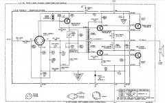

Based on the type of circuit this is, a single diode in each position is correct. The schematic indicates 0.62 volt drop across each, and that’s a single diode. The CFP output stage only requires two diode drops to bias. If the bias is too high at minimum setting, the diode used is too small. A higher current diode will have less voltage drop than a little bitty one, and result in lower bias current. If you can’t get it up high enough, use a smaller diode. Most of these circuits work well with 1N4001’s. High speed diodes are NOT required, as they always remain conducting because the VAS (Q803) operates class A.

Thanks. I tacked in single 1N4004's (what I had on hand) for CR803 and CR804. The bias remains unchanged at approximately 50mV. Try 1N4007's?
4007’s have even higher forward voltage drop, and would probably give a minimum bias across the emitter resistors 60 or more mV. Wrong way. Make sure the thermistor didn’t get damaged and open up - they are rather delicate. That would upset the bias range.
Got it. I'll try some 1N4001's.
Hadn't considered the thermistors. I'll need to lift a leg to check properly, but in circuit I'm measuring 63 ohms each.
Hadn't considered the thermistors. I'll need to lift a leg to check properly, but in circuit I'm measuring 63 ohms each.
Sorry but no.
Bias comes from the R813/815/821/823 network, where R813 Thermistor is the temperature sensing element and R815 is the adjustable one.
The stabistor clearly showing 6 diodes in series is not used for that but for short circuit protection and of course a single diode can not replace it.
Voltage drop per diode is 0.65V (hint: like any diode) so 6 diodes amount to 3.9V drop.
Way back then low voltage Zeners were not available or weird/expensive; today a 3.9V Zener is easy to source.
Even better, replace each with a single 1N400x or 1N4148 "pointing down) and a 3.3V Zener "pointing up" in series.
Yes, you have 0.62V across Q805/807 BE junctions, but not because of the Stabistor, which are useless for biasing (hint: temperature stable) and of course way too high voltage drop. (six diodes)
Short Protection duty:
Speaker current drops voltage across 0.47 ohm ballast resistors R635/637.
Said voltage rises driver transistor emitter voltage, its base voltage floats "one diode drop" above that.
When base voltage rises above Stabistor (or Zener) voltage, it is clamped and limits current there.
To what value?: stabistor voltage (6 diodes) minus driver Vbe= 5 diodes, = 5*0.65V=3.25V
Which across 0.47 ohm pass= 3.25/0.47= 6.9A which is a reasonable short circuit current clamping value for that amplifier.
No need for high precision, or temperature stability there, they used a Stabistor because it offered the needed voltage drop in an easy to use package, nothing further.
As of:
* R815 contacts/wiper are dirty , it "should" be adjustable down to zero, set it to 0 and measure residual resistance across it.
* NTC resistor spec is sightly high.
Don´t touch it, you will NOT get a proper replacement, instead tack solder a 470 ohm or 1K resistor across R821 ....any better?
If so, replace R821 by an 820 ohm one, should be enough.
Wait 5 to 10 minutes after soldering or blow a fan into the area, any residual soldering heat will cheat the thermistor.
Bias comes from the R813/815/821/823 network, where R813 Thermistor is the temperature sensing element and R815 is the adjustable one.
The stabistor clearly showing 6 diodes in series is not used for that but for short circuit protection and of course a single diode can not replace it.
Voltage drop per diode is 0.65V (hint: like any diode) so 6 diodes amount to 3.9V drop.
Way back then low voltage Zeners were not available or weird/expensive; today a 3.9V Zener is easy to source.
Even better, replace each with a single 1N400x or 1N4148 "pointing down) and a 3.3V Zener "pointing up" in series.
Yes, you have 0.62V across Q805/807 BE junctions, but not because of the Stabistor, which are useless for biasing (hint: temperature stable) and of course way too high voltage drop. (six diodes)
Of course, nowadays Zener diodes down to 2V7 are easy to find.The stabistor (also called a forward reference diode) is the technical term used to designate a special type of semiconductor silicon diode featuring extremely stable forward voltage characteristics. These devices are specially designed for low-voltage stabilization applications requiring a guaranteed voltage over a wide current range and HIGHLY STABLE OVER TEMPERATURE. ...... Devices are also available with multiple diodes connected in series inside a single package offering higher forward voltages than a single device but lower than those obtained using standard zener diodes.
Short Protection duty:
Speaker current drops voltage across 0.47 ohm ballast resistors R635/637.
Said voltage rises driver transistor emitter voltage, its base voltage floats "one diode drop" above that.
When base voltage rises above Stabistor (or Zener) voltage, it is clamped and limits current there.
To what value?: stabistor voltage (6 diodes) minus driver Vbe= 5 diodes, = 5*0.65V=3.25V
Which across 0.47 ohm pass= 3.25/0.47= 6.9A which is a reasonable short circuit current clamping value for that amplifier.
No need for high precision, or temperature stability there, they used a Stabistor because it offered the needed voltage drop in an easy to use package, nothing further.
As of:
2 possibilities:the bias can't be adjusted any lower than 50mV, when the spec is 15mV
* R815 contacts/wiper are dirty , it "should" be adjustable down to zero, set it to 0 and measure residual resistance across it.
* NTC resistor spec is sightly high.
Don´t touch it, you will NOT get a proper replacement, instead tack solder a 470 ohm or 1K resistor across R821 ....any better?
If so, replace R821 by an 820 ohm one, should be enough.
Wait 5 to 10 minutes after soldering or blow a fan into the area, any residual soldering heat will cheat the thermistor.
AFAIK, the only stabistors you can actually buy anymore are the Central Semiconductor CMXSTB400, which is four diodes in one SOT-26 package, and the NXP BAS17, which is a single diode in SOT-23.
I checked the bias trimmers at their zero setting, and measured 0.1 ohms.
I then clipped a 1k resistor parallel with R821, but no change to the bias.
(This was with a single 1N4004 still in place at CR803 and CR804.)
Mind you, this bias issue is with both channels. I feel like I'm missing something obvious that would cause what I'm measuring.
I then clipped a 1k resistor parallel with R821, but no change to the bias.
(This was with a single 1N4004 still in place at CR803 and CR804.)
Mind you, this bias issue is with both channels. I feel like I'm missing something obvious that would cause what I'm measuring.
I see the connection dot in the schematic when I blow the image up, and confirmed the connection on the PCB - those diodes are not the bias stack. Just the resistors, pot and thermistor. You could leave the diodes OUT for troubleshooting. Even if the thermistor were open, there shouldn’t be enough voltage drop in that 100 ohm resistor to generate 1.2 volts of bias at the minimum pot setting. Unless the current thru the VAS transistor were dead wrong. The usual failure mechanism (leaky bootstrap cap) would tend to reduce it - going the opposite way. Something else weird has got to be going on. How much voltage between the bases of the driver transistors are you actually measuring? Does shorting out the entire bias stack cause the bias on the emitter resistors to drop to zero?
I hope these were measured with respect to the negative supply and not ground. If respect to ground, then I think the problem is somewhere in the diff pair or mirror. What is the output voltage? You mentioned the problem is on both channels, if so it would be odd for the problem to be in both diff pairs or mirrors. This would then point to a common element in the circuits. Supplies or that zener.
This was with respect to ground.
Agree that it would be odd for the differential pair in both channels to have an issue. The zener had been replaced by someone prior to me with the incorrect value, so I subbed in a new 27V 3W. But the bias readings I'm getting were the same before and after. As for the power supply, I measure the B+ coming the driver board at +42V and the B- at 43.9V.
Agree that it would be odd for the differential pair in both channels to have an issue. The zener had been replaced by someone prior to me with the incorrect value, so I subbed in a new 27V 3W. But the bias readings I'm getting were the same before and after. As for the power supply, I measure the B+ coming the driver board at +42V and the B- at 43.9V.
HTH could CR801 803 be burned open? They are not "bias" (as JMF says, that is the NTC part). They normally never conduct. When the speaker is shorted and >7A current flows in output transistors, these diode-strings clamp the current. Then the diode strings have to carry "all" the current from Q803... which is clamped to 0.050 Amps. Even a 100mA small diode can carry that because half the time it will be zero.CR801, CR802, CR803, and CR804.... open.
I think you will find more problems. Even clamped <50mA, Q803 may be shorted.
I repaired a LOT of this generation Fishers. I got the modules cheap as factory reject. About half "could" be repaired on a teenager's experience and budget. But the vast piles of these things on the "surplus" market suggested that Fisher had a real design problem and was building rejects, or experiencing warranty failures, faster than they could fix them.
It is a shame this is not 2019 again. This begs for a LM3668 replacement. (Even if you had to replace the heatsinks?)
Something about that was nagging the back of my mind ... until it clicked: I guess they are not burnt at all!!!!!!!HTH could CR801 803 be burned open?
Multimeter diode test applies 2V or less and measures voltage drop , typically can´t even turn a Led ON (needing meager 1.9V) , so it will read a Stabistor OPEN both ways: 1 way it´s reverse biased and the other needs 3.9V .... no way José!!!!!
In good English: "reading open both ways does not mean they are open"
Confirming the suspicion:"WHY would they open anyway?"
MY MISTAKE:
all the time I was thinking R821=1k .... which it is not
Just saw it´s 100 ohm 😱
So, correct my suggestion to:
instead tack solder a 47 ohm or 100 ohm resistor across R821 ....any better?
If so, replace R821 by an 82 ohm one, should be enough.
Sorry.
Now try biasing range again.
As of the amp circuit, it´s not ´orrible by any means: it´s a classic 70s 80s Lin type power amp, checked values and are quite generic, even today I build similar ones by droves, since nothing "better" is needed or desirable for Guitar amps, go figure.
That said, it could have been poorly built ....
And IF they used house brand 2N3055/MJ2955 (not much else available way back then,specially as complementaries) they would have been beyond the safe range., some would have survived, others not so much.
That said, it could have been poorly built ....
And IF they used house brand 2N3055/MJ2955 (not much else available way back then,specially as complementaries) they would have been beyond the safe range., some would have survived, others not so much.
OK, I fouled up: I trusted the "open" report and I should not have. Working on these amps is part of why I would eventually lift a leg and get a 9V or 24V battery and a resistor on it, both ways.In good English: "reading open both ways does not mean they are open"
It does seem odd that they have diodes everywhere except the bias network.
There was a whole sequence of these, over price and over time. Single-ended disposable to really well SOA-protected. Good education for me. However Fisher shut their production line soon after, in part because Asian factories got good and cheaper (and ate their own rejects). (There may have been a lingering US production in the super-amp market.)
Devices were mostly private-number Motorola.
Still puzzled by your base voltage measurements. With no signal, they should be less than +-1.5 volts from ground. +40 volts suggests that the amp output is also nearly +40 volts from ground! Please verify the output voltage and have a relook at the base voltages. Something is not adding up.
Still puzzled by your base voltage measurements. With no signal, they should be less than +-1.5 volts from ground. +40 volts suggests that the amp output is also nearly +40 volts from ground! Please verify the output voltage and have a relook at the base voltages. Something is not adding up.
Yes, there's about +39V at both speaker outputs. Differential pair(s)?
There are lots of ways this might happen on one channel, far fewer with both involved. Time to not worry about bias settings and solve the big problem, large dc on the outputs.
This could be blown output transistors on the negative rail, preventing pull down of the output. How might this or another failure mode happen on both channels? Output might ha e been shorted to ground or another supply, in debugging the first blown channel the user swapped in the other channel and inadvertently blew it the same way. Next steps start with getting all the voltages on the output devices, base emitter and collectors.
I am not a fan of replacing stuff till it's maybe fixed. Let's actually figure out what's wrong first.
If the fuses in the output transistor emitters aren’t blown, then the outputs are probably ok. Shorted outputs would blow those, regardless if youre stuck to the rail or not. If they are shorted and one fuse is blown it would stick to the other rail. The only way not to blow fuses is if they are still good. Since both channels are doing the same thing, I’d start with what could affect both - such as R841 and CR805. If that stabilized supply went missing, it would stick both channels to the upper rail.
The output stage bias can only be made correct once you get it to center properly.
The output stage bias can only be made correct once you get it to center properly.
- Home
- Amplifiers
- Solid State
- Stabistor Sub for old SS Fisher?