Anyone ever use a VTA driver board on an EL84 amp?
I recently got a Heathkit SA2 I wanted to mess around with tubes for a bit so I started looking at mods to make to it.
I read great reviews on Bob Latino's VTA ST-70 low-gain driver board with constant current on the phase splitters. Being the bonehead I am, I thought the St70 and the SA2 used the same output tubes and built a replica of his circuit, P2P, on the SA2. I also added Shannon Park's EFB circuit to it while I was in there.
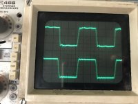
I even tuned the feedback a little, and checked the square-wave output at 10khz. Everything looked nice and squarish, and I think it sounds great.
I tested the output with an 8 ohm load, and it clipped at about 15wpc.
I started wondering why the ST70 puts 35wpc with the same circuit. That's when I realized they use different outputs.
So, I'm now wondering if I screwed up. Like I said, I think it sounds great, buy what do I know?
The attached waveform is 10Khz at 10w
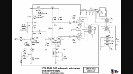
The schematic is the one I copied
Should I expect any problems with my odd setup?
I recently got a Heathkit SA2 I wanted to mess around with tubes for a bit so I started looking at mods to make to it.
I read great reviews on Bob Latino's VTA ST-70 low-gain driver board with constant current on the phase splitters. Being the bonehead I am, I thought the St70 and the SA2 used the same output tubes and built a replica of his circuit, P2P, on the SA2. I also added Shannon Park's EFB circuit to it while I was in there.
I even tuned the feedback a little, and checked the square-wave output at 10khz. Everything looked nice and squarish, and I think it sounds great.
I tested the output with an 8 ohm load, and it clipped at about 15wpc.
I started wondering why the ST70 puts 35wpc with the same circuit. That's when I realized they use different outputs.
So, I'm now wondering if I screwed up. Like I said, I think it sounds great, buy what do I know?
The attached waveform is 10Khz at 10w
The schematic is the one I copied
Should I expect any problems with my odd setup?
Attachments
Last edited:
The EFB is trademarked by Dave Gillespie, it's not designed by Shannon Park, who merely ran some tests on his ST-35. Anyway, the VTA driver should be fine in the SA-2, as long as you don't crank up the input too high or it will overload the EL84's, as it is intended for the larger EL34's.
As a general sort of guess, a good driver circuit capable of driving EL34s will have an even easier job driving EL84s. The trick is ensuring the loop gain and compensation is still sensible when applied to an EL84 output stage, as EL84s need a lot less drive. If the feedback isn't excessive and the thing is stable then it's probably fine!
Thanks for the replies Jazbo8 and Bigwill
Yup, its Dave Gillespie's EFB. Thanks for the correction. I get this stuff mixed up all the time. Credit where due; Dave and Bob are amazing for all they give to this hobby!
I haven't measured the gain yet, I'll do that next time I've got some spare time to haul the test stuff out of the closet. Is there a ballpark I should be in for the gain in an EL84 PP in ultralinear mode? I'm still using the 7.5k Ohm and 220pf feedback network from the V12 VTA driver schematic. I figured the 10k square wave looked OK and didn't change it. Do those waveforms look OK? I've gotten carried away with other amps I built and just lost interest. Trying to tread lightly with this unit. The slight oscillation in one channel appears to be a transformer issue. The square wave looks awesome at 1khz, BTW.
As for a overloading the EL84 outputs, I'm using Klipsch Forte II speakers rated at 99DBW in a smallish room, so I doubt it's ever over a watt at my listening levels. I imagine it'll be ok.
Yes, the 10kHz square wave response looks decent, but you should not have even a slight oscillation in one channel. You may need to tweak the NFB network a bit (or add a Zobel for that OPT) to get rid of it.
Anyway, since you have such efficient speakers, you might want to just go with triode output, and crank the bias up for mostly class A operation.
Anyway, since you have such efficient speakers, you might want to just go with triode output, and crank the bias up for mostly class A operation.
The triode output is a good idea, I'm going to try it out. Thanks.
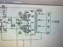
So, all I have to do is disconnect pin 9 of the EL84 from the OP transformer, and connect pin 9 to pin 7 via a 100 ohm resistor? I've seen schematics with and without the resistor, is it needed?
So, all I have to do is disconnect pin 9 of the EL84 from the OP transformer, and connect pin 9 to pin 7 via a 100 ohm resistor? I've seen schematics with and without the resistor, is it needed?
Attachments
Last edited:
So I triode strapped the EL 84s and listened to it for a while. I think it sounds a little better, kinda hard to say though. That aside, I want to leave it in a triode config, as the overall gain is a much better match with my speakers. I can turn the volume to 12:00 before its too loud now.
My new concern is the plate voltage on the el84s. Its at 405v, currently.
I drew the class A and AB load lines in push/pull triode and if I did it correctly, I need to drop my B+ to around 250v to make it a true class a output. Does this sound correct? The opt primaries are about 7k ohm.
Im currently running 405v at 28ma
Would 250v at 45ma be in the sweet spot for class a?
Im new to tubes so please forgive me if my terminology is off
Last edited:
You can also decrease the gain of the amp by adjusting the feedback network (though there are some limits on this).So I triode strapped the EL 84s and listened to it for a while. I think it sounds a little better, kinda hard to say though. That aside, I want to leave it in a triode config, as the overall gain is a much better match with my speakers. I can turn the volume to 12:00 before its too loud now.
405V is really quite high for an EL84, though you see it done all the time. Since you aren't angling for absolute maximum power, perhaps consider dropping down to 300V as a compromise.My new concern is the plate voltage on the el84s. Its at 405v, currently.
I drew the class A and AB load lines in push/pull triode and if I did it correctly, I need to drop my B+ to around 250v to make it a true class a output. Does this sound correct? The opt primaries are about 7k ohm.
The thing about A vs. AB can be a bit arbitrary, especially with tubes. If you study the EL84 datasheets, you'll see AB and B operating points given that have the same plate/screen voltages and load resistances; all that changes is bias current and method of biasing.
You are correct that where you are biased now, you're a bit close to the 0mA cutoff on the plate curves. Try redrawing your load lines for 300V/40mA and 250/40mA. If you've left the feedback loop in place, there's some room for imperfection in this process.
The easiest thing would indeed be to just go with the book triode values for the triode class A amplifier since your OPT is conveniently the correct impedance for such an implementation.
Thanks for the input, audiowise.
I think you're onto something with a 300v compromise.
Im currently using a CRC filter after the recifier (the first C is the high at 68uF)
If i use a correctly implemented LCRC filter i bet that would get me close to 300v. (280ish if my math is right)
I guess the first step is to sort my b+ voltage then calculate the bias current.
Can you recommend a textbook for my setup. I looked some online without much luck (other than the "oddwatt" design which seems similar and uses 210v b+
Once you get the B+ sorted out, you might try triode mode with no or very little feedback. It's what made me a tube amp fan.
The EL84 datasheet gives triode parameters that are about right for what you want.Can you recommend a textbook for my setup. I looked some online without much luck (other than the "oddwatt" design which seems similar and uses 210v b+
Try PSUD for power supply modeling to help you narrow down what a choke input filter will do for you.
- Status
- Not open for further replies.
- Home
- Amplifiers
- Tubes / Valves
- ST70 VTA driver with Heathkit SA2 EL84