I'm looking for a good Square Wave oscillator, that I can build.
It's needed for testing standard audio frequency appliances , and for checking D/A converters.
I'd like to have a super clean shape...no rounded or peaked edges, and, level and ...well you know.......square.
Although I have not yet tried a 555 timer, someone told me a flip-flop and a buffer would be much better.
....or is it possible to stick something on the output of my low distortion sine generator ?
=RR=
It's needed for testing standard audio frequency appliances
, and for checking D/A converters.I'd like to have a super clean shape...no rounded or peaked edges, and, level and ...well you know.......square.
Although I have not yet tried a 555 timer, someone told me a flip-flop and a buffer would be much better.
....or is it possible to stick something on the output of my low distortion sine generator ?
=RR=
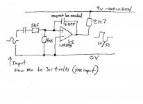
An externally hosted image should be here but it was not working when we last tested it.
Use R5/R2 to adjust pulse width of square wave, R7 to set
frequency. use another op-amp with output attenuator and
dual regulated power supplies (+/- 12VDC..pins 4/7) for
a better unit.
OS
Thanks ostripper .
However, I may be wrong, but I have my doubts that the square emanating from an opamp, will meet my desire for a "true" sharp square.
I could try it....looks easy.
=RR=
However, I may be wrong, but I have my doubts that the square emanating from an opamp, will meet my desire for a "true" sharp square.
I could try it....looks easy.
=RR=
op-amps slew rate is only limiting factor, it is most likely
better than most SS amps. A better op-amp (ne5534) ,would
beat many audio amps in slew rate.
better than most SS amps. A better op-amp (ne5534) ,would
beat many audio amps in slew rate.
ostripper said:op-amps slew rate is only limiting factor, it is most likely
better than most SS amps. A better op-amp (ne5534) ,would
beat many audio amps in slew rate.
Joking? 😀
741 = 1v/uS
NE5534 = 13v/uS
"blameless" amp = 10-20V/us before optimization
( from book-D.self)
consumer ht receiver= rarely more than 15v/uS
audiophile amp (and our DIY amps) 30-40v/us
heck, use a max477 op-amp w/ 1100 v/us slew
but at audio freq. above circuit w/ hysteresis
will give very square wave.
NE5534 = 13v/uS
"blameless" amp = 10-20V/us before optimization
( from book-D.self)
consumer ht receiver= rarely more than 15v/uS
audiophile amp (and our DIY amps) 30-40v/us
heck, use a max477 op-amp w/ 1100 v/us slew
but at audio freq. above circuit w/ hysteresis
will give very square wave.
If you look at some of the graphs that Nelson puts out for, say, the F5 amplifier, he is illustrating bandwidth with a 200kHz square wave. That's pretty brutal on any audio amplifier.
A standard, government issue multivibrator isn't stable enough for testing. if you have a sine generator or a decent sound card program you can use output to drive a high speed amplifier (Current feedback). Clip the output with a pair of diodes. The output is pretty square at this point. This somewhat square output is fed to a high speed comparator. I have used an Intersil transistor array, (1) but you could use a high speed comparator from ADI, Linear Tech or Tex Instr) It will give you an extremely nice square wave.
Square wave generators like to have their cabling and termination impedances etc. all match up. You might want to buffer the output with another current feedback amplifier. When you get to high speeds you get standing waves on the cables etc.
(1) the basic idea is shown on an intersil application note "Measuring Phase".
AndrewT said:a comparator would be better still. They are designed to change state fast.
That's probably what I would look at for a quick implementation. Look up some data sheets, for ex LM339, they always show seem to show square wave oscillators and sine/ square convertors.
One comparator and one opamp should be all you need to make a "data slicer" that will maintain a 50/50 duty cycle with a wide range of input amplitudes from a sine generator.
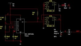
Easy. A 555 oscillator of arbitrary duty cycle. There are examples in the datasheet. But.... Read on...
Now, to make it exactly 50% duty cycle and have nice sharp rise and fall times, drive a CMOS (not TTL) binary counter, and take the output from the first stage. This will give you half of the oscillator frequency at exactly 50%. Use a pot on the output to adjust level...
The 4020 is a possible choice. 74HC or 74AC are even better and will give faster rise/fall times.
Use of an easily available comparator, like the LM339, would not be a good choice because the fall time will be fast, the rise time will be slow due to the open collector output. The 555 has the same problem, but the counter on the output makes it go away. There are comparators available that have a push-pull output, but the solution I mention will work like a charm.
Good luck,
John
The 4040 is also a good choice. I'd personally go with the 74HC393 which will give you a whopping 450V/us slew rate.
Thanks everyone.
There is a lot in these forums about building decent Sine waves, but not much about Square Wave generators, so let's try.
Soundcards don't quite extend high enough for evaluating their own D/A converters (which my friend is trying to do right now), so an outboard solution would be nice, even if it involves building "back terminated" cables to ensure impedance/phase accuracy.
If anyone wants to draw a quick schematic, I'll volunteer to build some of these designs and do a mini "shootout", and post the results. (that is, IF my usual "point to point" proto building technique won't hinder the performance too much...I'm pretty good at it though http://i5.photobucket.com/albums/y177/Midiot/DSCN2897.jpg }
I have some high-speed opamps (current types)
AD811
EL2020
as well as fast comparators:
AD790 (45 ns)
LM361 (20 ns)
Maxim 900 series (10 ns ?)
Flip-Flops:
SN74LS109A
MC14013B
CD4013B
Other:
555 timer
F163a counter
CD40106 CMOS hex schmitt trigger
CD4047 monostable/astable multivibrator
Odd Balls:
AD654 V/F converter
OPA660 OTA
LM565 PLL
There is a lot in these forums about building decent Sine waves, but not much about Square Wave generators, so let's try.
Soundcards don't quite extend high enough for evaluating their own D/A converters
(which my friend is trying to do right now), so an outboard solution would be nice, even if it involves building "back terminated" cables to ensure impedance/phase accuracy.If anyone wants to draw a quick schematic, I'll volunteer to build some of these designs and do a mini "shootout", and post the results. (that is, IF my usual "point to point" proto building technique won't hinder the performance too much...I'm pretty good at it though http://i5.photobucket.com/albums/y177/Midiot/DSCN2897.jpg }
I have some high-speed opamps (current types)
AD811
EL2020
as well as fast comparators:
AD790 (45 ns)
LM361 (20 ns)
Maxim 900 series (10 ns ?)
Flip-Flops:
SN74LS109A
MC14013B
CD4013B
Other:
555 timer
F163a counter
CD40106 CMOS hex schmitt trigger
CD4047 monostable/astable multivibrator
Odd Balls:
AD654 V/F converter
OPA660 OTA
LM565 PLL
I have 4024b.jgedde said:The 4040 is also a good choice. I'd personally go with the 74HC393 which will give you a whopping 450V/us slew rate.
What to do with the unused pins ?
Looks nice, Mooly.
=RR=
redrabbit said:
I have 4024b.
What to do with the unused pins ?
=RR=
Unused input pins get tied to ground or Vcc.
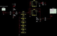
jgedde said:Try this... It uses what you have in stock. Don't forget power and ground on the 4013 (not shown).
Cheers,
John
Alright, I'll try those next.
Did you draw up those tonight ?
Thanks, I appreciate it !!
jMooly said:This works,
would form the basis of a nice little project. As jgedde says the output is affected by capacitive loading so a buffer required. It doesnt come much simpler though.
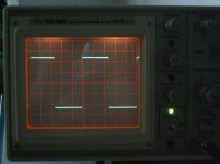
Yes, it does work.
I used an AD790...it has a couple of extra pins to deal with.
My scope had a bit of trouble triggering it at low freq, at under 200 hertz.
Drawing
=RR=
- Status
- Not open for further replies.
- Home
- Amplifiers
- Solid State
- Square Wave needed