Wirewound SQP (cement) resistors are well-known to everyone. They can be found everywhere in audio equipment, for example, in crossovers used in speakers ranging in price from $100 to $100,000. Externally, they all appear to be roughly the same. However, upon careful examination, it becomes apparent that they can vary significantly. Some of them exhibit substantial nonlinearity (several times higher than the nonlinearity of a good transistor amplifier), which is attributed to the physical properties of the wire alloy used to construct these resistors.
To test various resistors for linearity, I have assembled a setup according to the provided schematic, where the tested resistor is denoted as R_DUT.
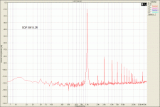
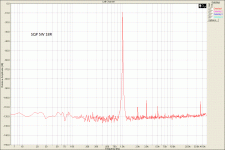
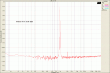
As evident from the measurement results, certain SQP resistors introduce a significant amount of harmonics (distortion) into the test signal, and the spectrum of this distortion is dominated by odd harmonics, which are well-known to be the most unpleasant for the human ear.
Metal film resistors do not produce measurable distortion.
It can be observed that the amount of distortion produced by different SQP resistors also varies. Some SQP resistors generate minimal distortion. What is the reason for this?
I have discovered that high distortion is characteristic of resistors wound with wire made of an alloy containing a significant amount of magnetic material (most likely nickel). Conversely, resistors wound with non-magnetic or weakly magnetic wire do not introduce substantial distortion.
What type of wire is used in the crossover resistors of your new expensive speakers? You can verify this yourself using a powerful magnet.
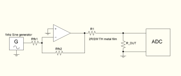
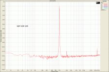
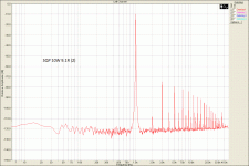
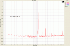


Here's some anecdotal evidence that supports this. I built a high power dummy load for testing power amps. I used two 4 ohm 300W wirewound resistors, which could be configured at 8 ohms (in series), two separate 4 ohms, or 2 ohms in parallel. These resistors are 35mm diameter and 220mm long wound on a tubular ceramic former.
Using a Tektronix SG505 sine generator and AA501 distortion analyzer (good to 0.001% THD) I was dogged with anomalously high distortion on the amps I was testing. I eventually built up an array of Vishay TO220 packaged metal film resistors on large heatsinks, which worked with no additional distortion problem.
I've just hauled my original dummy load out - and the resistance element is strongly magnetic, and the solder tags are exceptionally magnetic.
On the basis of that, I can well believe that a strongly magnetic resistance element can give rise to a high level of harmonic distortion.
I have used the distortion inducing resistors in applications where harmonic distortion is not a problem - but they are now always used in those applications.
As the saying went (in broadcasting back in the early 70's) - Get the Iron OUT!
A couple of quotes from Lars Risbo:
"resistors are not created equal - some are more nonlinear than others. We had a whole production batch of Eigentakt amps failing end of line test because the wrong type of resistor was used in one single location on the PCB"
"failing due to THD at -105dB instead of the usual -115dB. Degree? measurable using std lab equipment such as an AP analyser. Same goes for capacitors and inductors. Even speaker binding posts with ferrite magnetic materials can give measurable distortion. Why is this so controversial? We have tons of measurements on this and may publish at some point. meanwhile, remember that absence of evidence is not evidence of absence"
https://www.diyaudio.com/community/threads/placement-of-resistors-in-signal-path.384534/post-6981182
https://www.diyaudio.com/community/threads/placement-of-resistors-in-signal-path.384534/post-6981506
Wirewound resistors sometimes have a high distortion level. This has been discussed on the forum, here for example, and elsewhere.
There seems to be a correlation with the magnetism of the resistive element, but I think it is just a correlation, not a cause to effect relationship. The mains culprit seems to be the contact between the terminals and the resistive element, and it is probably more difficult to ensure a good quality, purely ohmic contact with some resistive alloys which also happen to be magnetic
There seems to be a correlation with the magnetism of the resistive element, but I think it is just a correlation, not a cause to effect relationship. The mains culprit seems to be the contact between the terminals and the resistive element, and it is probably more difficult to ensure a good quality, purely ohmic contact with some resistive alloys which also happen to be magnetic
Didn't there used to be some popular high end resistors that used copper endcaps? IIRC the endcaps loosened over time so were unreliable. The manufacturer switched to steel endcaps which stayed secure, but the sound changed for the worse. It caused some people to stop using the new version.
If the wire is ferromagnetic it will exhibit non-linearity dependent on the current level - for uA or mA signals this is not normally significant or even measurable, but at high current (amps) its definitely a thing, the non-linearity of the inductance of the wire due to ferromagnetic behaviour is becoming visible as the magnetic flux density increases. This is true whether or not the device is inductively wound, note, as there is inductance directly in the wire itself.
The standard resistance wire(*) alloys, nichrome, constantan, manganin all claim to be non-magnetic, although they contain ferromagnetic elements like nickel and anti-ferromagnetic elements like chromium - perhaps some resistance wires use formulations that are magnetic? Or the alloy specification is loose enough that sometimes it is? Or some cheap devices use steel(!?)
Its well known than many terminal posts and relay frames are steel and have measurable distortion due to ferro-magnetism for high-currents (speaker wiring, basically).
Poor bonding of terminations in resistors can give rise to distortion. Resistance alloys don't solder I believe, so some sort of spot weld / cold weld / brazing is needed for wire-wound resistors - if that is low quality then bad things can happen.
(*) Resistance wire has a low temperature coefficient of resistance, unlike pure metals which have large positive coefficients, and some resistance alloys handle very high temperatures in air without oxidizing away so they can be used in electric heaters.
I think you are right about the solderability. At least the last time I tried to solder resistance wire, decades ago with tin-lead solder, it didn't work out.
As an amateur scientist I'm always thinking "what causes this," in this case what causes ferromagnetic material to cause distortion? It's apparently that the changing current in a wire (through generating a changing magnetic field) flips magnetic domains in a ferromagnetic material, which then generates their own change in the magnetic field that gets picked up by the wire. It tends to be at a low level, low enough that many people (I've seen here) dismiss the idea that something like a magnetic binding post could cause a change in the current flowing through it.
I've wanted to experiment with this, but this guy on Youtube beat me to it. Here the effect is so large that you can hear it through a cheap guitar amp!
I've wanted to experiment with this, but this guy on Youtube beat me to it. Here the effect is so large that you can hear it through a cheap guitar amp!
Some decades ago i took a closer look at some low resistance "çement" resistors because of theyr unreliabe performance under high pulse current load. The ones i opened up had crimped on connections. The wire was wound onto bundled glassfiber and simply connected by crimping a meta cap over the winding ends. The connection wires where brazed to the caps. The observed low heat capacity coupled with unreliabe connections was reason enough for me to avoid those type of resistors and get me a stach of (back then) much better made resistors by philips, low tempco wire wound on a ceramic body, brazed connections, glass covered reliable construction. I do not know how cemented resistors are built today but if the construction is still as back then, no matter magnetic or not, i would avoid them for reasons of unreliabilty alone.
Problems with resistor distortion/noise can occur even with metal thin film resistors believed to be of very high quality. IME even if numerically small, the effects may be audible in some sensitive audio applications. Some info regarding causal mechanisms attached.
Attachments
Recently, I used some MOX resistors of 1 ohm in series with my tweeters. I had sibilance issues that were not there prior their addition. When I swapped to cement/sandcast resistors, the problem disappeared.
- Home
- Design & Build
- Parts
- SQP (cement) resistors nonlinearity measured and explained