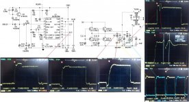
Looks like a commercial design from the way the circuit is drawn.
Why is the "spike" a problem ? Is the unit faulty in some way.
You have to be very careful in just what you call "ground" too, moving the connection to avoid it being influenced by circuit resistances etc as the very high currents have a real effect on measurements..
Why is the "spike" a problem ? Is the unit faulty in some way.
You have to be very careful in just what you call "ground" too, moving the connection to avoid it being influenced by circuit resistances etc as the very high currents have a real effect on measurements..
Thank you for the reply. The spike increases the output voltage, causing problems. Can this spike be a ringing of the ferrite ?
Could the ferrite itself cause the spike ? Or is it the way the coil is wound ?
ferrite material N87 R 50.0 x 30.0 x 20.0 http://www.epcos.com/inf/80/db/fer_07/r_50.pdf
Could the ferrite itself cause the spike ? Or is it the way the coil is wound ?
ferrite material N87 R 50.0 x 30.0 x 20.0 http://www.epcos.com/inf/80/db/fer_07/r_50.pdf
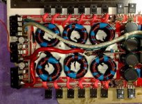
I suspect layout problems. You must confine all high currents to the intended path. A stray amount of current can cause spikes.
How about a photo of the circuit with notes showing where the parts are...
How about a photo of the circuit with notes showing where the parts are...
Is this something you have made yourself ? or is it a faulty commercial product ?
When you say the "output voltage increases" what do you mean ? You haven't shown the secondary connections, feedback etc. Do you rectify the outputs ?
When you say the "output voltage increases" what do you mean ? You haven't shown the secondary connections, feedback etc. Do you rectify the outputs ?
My problem is the large input capacitance of irfp2907.
I cannot find a good gate resistor value. (resistor + diods)
I have tested values between 22 and 100 ohms, all with bad results.
The lower value resistor I'm using, the more obvious the problems are.
I cannot find a good gate resistor value. (resistor + diods)
I have tested values between 22 and 100 ohms, all with bad results.
The lower value resistor I'm using, the more obvious the problems are.
Last edited:
Please help me, this problem is getting irritating. I'not able to drive irfp2907pbf.
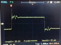
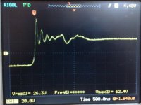
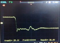
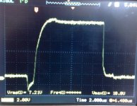
The spike is the main issue because it causes an increase in voltage after the rectifying bridge and I don't want this.
I've tried gate resistors with values between 2 and 100 ohms + a diode for closing, I've even tried a PNP tranzistor for forced closing and still no help.
I've even modified the number of windings on the ferrite and still no result.
The mosfet opening / closing circuit seems to be ok but I get a ringing at 2 different frequencies. I can tame the 4Mhz ringing with a snubber but for the life of me I can't tame the 1.1Mhz ringing.
Please help, i'm on the edge of giving up with the project.
wave form on primary
Attachments
well try diffrent snubber.
Also when I had some load to smps, this was much better, idle was worse, and its not bad anyway... do you have snubbers on pri and sec windings? each to gnd?
Also when I had some load to smps, this was much better, idle was worse, and its not bad anyway... do you have snubbers on pri and sec windings? each to gnd?
Sum ting wong. There must be a "secret" inductor somewhere. Can you get a much bigger shot of the board? Both sides? What about the rectifier circuit?
Last edited:
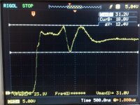
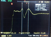
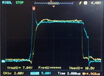
top pictures are without snubber
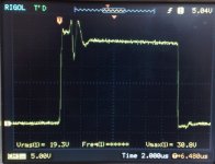
whit snubber 22nF + 10 ohm/3w on primary (not GND), whit no load.
whit snubber 22nF + 10 ohm/3w on primary (not GND), whit no load.
Attachments
Last edited:
What's the deal with the first and third waveform shots you last posted? Presumably those are both sides of the push-pull? The last one looks passable. If you have the same circuit and are getting different results, then you don't have the same circuit. The layout must be an issue.
(well I meant the post before the last)
(well I meant the post before the last)
Last edited:
Whit the same pcb and irfp1405 the problems is gone!
I guess my problems is the large input capacitans of irfp2907pbf.
What can I do?
I guess my problems is the large input capacitans of irfp2907pbf.
What can I do?
I meant can you post a shot of gate and drain pulses on one oscillogram. I'm trying to figure out exactly what's starting to happen 1uS after the rising edge of the drain voltage. Try the gate of one side drive and the drain of the other.
- Status
- Not open for further replies.
- Home
- Amplifiers
- Power Supplies
- spike problem !