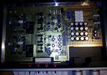
I have a DMC-10 Gamma that has been in storage for many years. I decided to listen to it and it works but has a dim power LED. It also doesn't seem to sound as good as I remember. I removed the top and found a broken cap as well as a few swollen ones. I would like to replace them all if possible but it's going to be difficult to remove the board. The interior is so lovely I want to keep it that way. The caps are all 35uf 50VDC and appear to have paper inside, they have Spectral written on them and most have the no. 8808 with a few having 8813. Any good suggestions would be appreciated.
Post an image?
What color is the dielectric material of the PCBs??
I ask because on some of the Spectral stuff a very high quality material was used that had a low melting temp, making work on them more difficult.
In general, I'd replace them with newer higher quality very low ESR and high temp rated caps, preferably of higher voltage rating than the stock. There are also "audio" grade electrolytics with similarly good characteristics. Digi-Key & Mouser and the other industrial suppliers have them. The newer caps tend to have smaller footprints, so higher voltage ratings are likely no larger than the originals.
I'd replace 100% of all of the electrolytics if you have found more than one or two that have gone south while sitting around. I'd NOT fire it up with bulging caps.
The codes are likely date codes, ignore.
_-_-
Thanks Bear. I'll post an image tomorrow as I'm not at my computer now. I did fire it up before opening it in a small system that's how I knew it didn't sound it's best. But I won't again 'til it's fixed. The dielectric appears to be paper.
Attachments

paper? the printed circuit boards?
IF they are white, then I believe they are a type of expanded polystyrene. Are they white?
IF they are white, then I believe they are a type of expanded polystyrene. Are they white?
Attachments
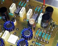
The boards are gold plated, the caps appear to be whitish paper inside, black outside as the pics should show.
oops, just saw ur pix as I posted.
Looks like standard fiberglass PCB.
They are double sided with through-hole "vias".
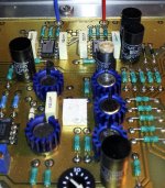
I'd replace them all. You'd want a temp controlled soldering iron and a good way to SUCK the solder out of the holes without overheating the boards. Mark the boards with the polarity, unless of course the boards are marked and you can see that.
Afaik, these are all power supply related caps, the signal path (except for RIAA or tone controls) is all DC coupled. So, high-temp rated, low ESR caps preferably with a slightly higher voltage rating, form factor to fit (pin spacing the same would be nice). Voltage rating 75-100vdc (higher IF they fit nicely).
Ought to be ok after that, unless something else went south.
The power supply caps are of some concern, but appear to be a different manufacturer.
Maybe someone else reading has experience with these particular caps. I'd likely leave them be, but no reason not to replace them assuming the cost is not to high and you can desolder without damaging the board.
If I remember right the original DMC-10 had an outboard power supply.
Looks like standard fiberglass PCB.
They are double sided with through-hole "vias".
I'd replace them all. You'd want a temp controlled soldering iron and a good way to SUCK the solder out of the holes without overheating the boards. Mark the boards with the polarity, unless of course the boards are marked and you can see that.
Afaik, these are all power supply related caps, the signal path (except for RIAA or tone controls) is all DC coupled. So, high-temp rated, low ESR caps preferably with a slightly higher voltage rating, form factor to fit (pin spacing the same would be nice). Voltage rating 75-100vdc (higher IF they fit nicely).
Ought to be ok after that, unless something else went south.
The power supply caps are of some concern, but appear to be a different manufacturer.
Maybe someone else reading has experience with these particular caps. I'd likely leave them be, but no reason not to replace them assuming the cost is not to high and you can desolder without damaging the board.
If I remember right the original DMC-10 had an outboard power supply.
The square array of caps in the pix are undoubtedly for the power supply. The associated electronics nearby are likely regulators.
Power Supply Questions
I will be acquiring a DMC-6 soon, minus the power supply. I am hoping someone can confirm the power supply pin outs and voltages. My detective work shows that they would have used about a 30 watt transformer with a center tapped 25.2 volt with dual secondaries. One channels power pins appear to be 3 and 4 on the 5 pin DIN. I have not been able to confirm any of this though. Can someone with more information step in?
Thanks, Don S
- Status
- Not open for further replies.
- Home
- Amplifiers
- Solid State
- Spectral DMC-10 Repair Help