I am wondering if this idea has been explored and is worth it?
The idea is to use rubber gaskets to sepoerate the front face of a speaker cabinet (with its virbrating drivers) from the rest of the speaker cabinet, to reduce vibration.
With this idea the only direct wood wood connection is the screws, unless I used very strong silicone gasket glue or some other selant like Selleys 300g Clear ArmourFlex Adhesive Sealant | Bunnings Warehouse
Thanks for any feedback.
Added on after reading: Disclaimer, "I am a beginner at this." Yes, very helpful posts below. I can see the LS3/5A had a baffle gasket, like Loudspeaker Gasket Baffle sealing strip self-adhesive 6mm wide applied as in http://www.g4dcv.co.uk/ls35a/pics/35atopsection.pdf . Then also for the LS3/5A to isolate the driver from the baffle like with LS3/5a BLACK PLASTIC CHANNEL STRIP for sealing B110 front edge. Not found pictures, but understand can isolate driver bolts, with O ring and in grommets. I also read this article on audiopress.com, which cautioned about a non solid connction which can affect sound clarity.
Attachments

Last edited:
It's a great idea, broadly speaking, because sound does get from the baskets to the cabinet. I'd want to damp that panel though. Silicone is compliant, and while sometimes it has shown to be very useful it doesn't have high damping qualities. While you're at bunnings, maybe get some soft polyurethane adhesive.
Yes, it has been explored. Since about the seventies of the last century. There even was a time that KEF sold their CS-units with appropriate dampers for mounting them on the baffle, consisting of a soft gasket and mounting bolts in grommets. Look for old publications from the BBC and old magazines like Wireless World. The mounting of the B110 in the LS3/5A also was more or less decoupled.
Decoupling the drivers from the baffle is the better way anyway. Resonances in the baffle aren't exactly what you want either. The main challenge is aiming at the right frequency range with the right amount of damping. Simply mounting some rubber gasket will not do.
Decoupling the drivers from the baffle is the better way anyway. Resonances in the baffle aren't exactly what you want either. The main challenge is aiming at the right frequency range with the right amount of damping. Simply mounting some rubber gasket will not do.
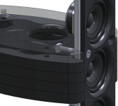
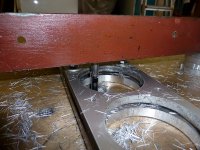
It's much like what I have done with my baffle construction, an outer baffle, isolated from the inner baffle that holds the driver(s). Flexible gasket between inner baffle and enclosure. Damping butyl rope (remains flexible) between inner baffle and outer baffle. Bolts hold it in place, under the bolt heads are rubber o-rings to further isolate them from the baffle...

The inner baffle, with drivers attached to them is floating between the enclosure and outer baffle with damping material between them.
My baffles are made of aluminium but the idea is similar. I cut them with a router and lots of lubrication (I used WD40).

The inner baffle, with drivers attached to them is floating between the enclosure and outer baffle with damping material between them.
My baffles are made of aluminium but the idea is similar. I cut them with a router and lots of lubrication (I used WD40).
Attachments
Last edited:
I Have used these following products to help reduce driver basket vibration being transferred to the enclosure,
Masonry Plugs, Anchors & Fixings - online | RS Components
Sorbothane 1mm Sheet or Film w/Adhesive 100*150mm, 4″*6″, 50 duro – Stop Vibration Online
One On One 48mm x 5m Heavy Duty Double Sided Sealing Tape
cheers
Masonry Plugs, Anchors & Fixings - online | RS Components
Sorbothane 1mm Sheet or Film w/Adhesive 100*150mm, 4″*6″, 50 duro – Stop Vibration Online
One On One 48mm x 5m Heavy Duty Double Sided Sealing Tape
cheers
i think you are maybe overthinking things.
there are loads of band/pa/disco large speakers without any rubber membranes.
the back of the cone will apply sound waves to back of cabinet anyway.
there are loads of band/pa/disco large speakers without any rubber membranes.
the back of the cone will apply sound waves to back of cabinet anyway.
I once wanted to follow a similar idea and wanted to know how much (unwanted) air gets displaced with different parts of the cabinet perfectly rigid and others elastic in a highly idealized setting. (Not sure is elastic is actually the correct term here.) Let’s say you have a SB29NRX and use it in a 51l box as in one recommendation on their site. For simplicity reason lets take a cubic box which would then have roughly 37 cm length in each dimension. Using 16 mm birch, each panel would weigh about 1.5 kg and the whole cabinet 9 kg (so-far all numbers rounded generously). The chassis itself weighs 5.4 kg bringing the total weight to 14.4 kg. The chassis has 58.9 g moving mass and 22 mm linear travel according to their datasheet.
So, what happens if the whole cabinet is perfectly rigid and the chassis is also mounted rigidly to the cabinet but the cabinet as a whole is on elastic rubber feet? When the moving mass (58.9 g) is moved from one peak excursion to another the cabinet as a whole (14.4 kg) has to move 0.09 mm to compensate. In this back and forth move the front and the back will cumulatively displace 24.6 cm³ of air (= 2 x 37 cm x 37 cm x 0.09 mm).
When everything is rigid (including the feet) except for the connection between front panel and the rest of the cabinet, the excursion will be 0.19 mm (front panel + chassis = 6.9 kg) and the displaced volume 25.7 cm³ (= 37 cm x 37 cm x 0.19 mm).
When the cabinet is rigid except for the mounting of the chassis to the front panel only the corpus of the chassis will compensate for the excursion. It will move 0.24 mm. The volume of the unwanted displaced air can in this case only be roughly estimated. The outer diameter of the chassis is 290 mm and the piston area 311 cm². If everything else (349.5 cm²) is contributing to displace air this would yield 8.4 cm³ (= (29 cm ^2 * pi / 4 – 311 cm²) * 0.24 mm)
Again, this is super idealized and doesn’t consider any other weight in the cabinet from the crossover or stuffing, it also doesn’t consider the position where this displacement is happening. I assume the further away from the chassis the more likely is it disturbing to the listener while radiation from the mounting plate of the chassis presumably mainly affects the directivity and won’t noticeably colour the sound. But based on these considerations I think it is unlikely that there is a huge benefit to decouple the front plate. Decoupling the chassis from the cabinet seems more useful.
Methods like this appear to address the important issue of mechanical vibration transferred directly from the driver basket to the cabinet. BTW, some in the past who have experimented with soft mounting have reported that too soft can create problems.
I have been wanting to try 'magnet mounting'. Magnet glued or clamped to a round piece of concrete filled pipe (or similar heavy and rigid material) with the same diameter as the magnet, and the other end of the heavy piece bolted to the rear wall of the speaker.
A compliant rubber seal or similar to seal the driver to the baffle.
If the mass of the concrete is fairly high, and rear wall reasonably stable, it should be a nice way of doing it?
A compliant rubber seal or similar to seal the driver to the baffle.
If the mass of the concrete is fairly high, and rear wall reasonably stable, it should be a nice way of doing it?
A solid dense material such as concrete will transmit vibration really well. Vibration is best mitigated through discontinuities, not mass. A dense mass semi rigidly decoupled to the driver in the way you’re describing will also effectively transmit low frequency (high energy content) to the cab
I just don’t understand what you are trying to achieve with the concrete tube?
I just don’t understand what you are trying to achieve with the concrete tube?
@romus:
I think this might work pretty well, but not for the reason you'd imagine.
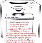
If I understand your drawing correctly, you want the adhesive to absorb the vibrations produced by the chassis acting more or less like a mechanical low-pass but due to the huge contact area you push the "crossover frequency" way up and allow more frequencies to pass than when using a smaller plate. (I dont know a lot about this so maybe I am completely wrong but I am sure you can do some research.)
On the other hand you just constructed a constrained layer damping arrangement. When the plates deform due to vibrations, the glue in between will be subjected to shearing and will absorb a lot of energy. Therefore there will be much less vibrational energy able to propagate to other plates of the cabinet or the surrounding.
To get the best of both worlds it may be advantageous to cut the inner plate so that you have a small mounting ring for an effective mechanical filter and a large, stiff plate for constrained layer damping.
I think this might work pretty well, but not for the reason you'd imagine.
If I understand your drawing correctly, you want the adhesive to absorb the vibrations produced by the chassis acting more or less like a mechanical low-pass but due to the huge contact area you push the "crossover frequency" way up and allow more frequencies to pass than when using a smaller plate. (I dont know a lot about this so maybe I am completely wrong but I am sure you can do some research.)
On the other hand you just constructed a constrained layer damping arrangement. When the plates deform due to vibrations, the glue in between will be subjected to shearing and will absorb a lot of energy. Therefore there will be much less vibrational energy able to propagate to other plates of the cabinet or the surrounding.
To get the best of both worlds it may be advantageous to cut the inner plate so that you have a small mounting ring for an effective mechanical filter and a large, stiff plate for constrained layer damping.
I am wondering if this idea has been explored and is worth it?
The idea is to use rubber gaskets to sepoerate the front face of a speaker cabinet (with its virbrating drivers) from the rest of the speaker cabinet, to reduce vibration.
With this idea the only direct wood wood connection is the screws, unless I used very strong silicone gasket glue or some other selant like Selleys 300g Clear ArmourFlex Adhesive Sealant | Bunnings Warehouse
Thanks for any feedback.
Its a good idea. BTW I never use screws in cabinets as this transfers vibrations between the panels (front, sides, back) in a cabinet. I only use builders glue to keep the box together. Also try to minimize the baffle where the drivers are attached. You can divide the baffle in parts to reduce the transferred vibrations.
- Home
- Loudspeakers
- Multi-Way
- Speaker front face design