Hi All,
Thought I'd share my latest meddlings.
Basically, I have been feeding my JLH 96 with a DAC via a passive pre. My passive pre has been either a linear 10k potentiometer, or a nice Alps 50k potentiometer. The linear is the right kind of impedance, but cannot be used quietly because of it's taper, and the 50k alps is lovely, but seemed to sound lifeless.
So, I thought I'd try and build an active buffer stage for my Alps pot, and call it a preamp 🙂
I set myself the rule that it needed to be done completely free of charge - using only bits I had lying around. Thankfully I did have some nice bits and bobs, although some bits are a bit overkill (120VA 15-0-15 toroid, 2x10,000uF 63v Cerafines), and some possibly not good enough (317/337).
The design is based on one of the Naim preamp schematics found on acoustica.org.uk (if you have a look at the Naim preamp tweaking page...). I used a similar design as a headphone amplifier years ago and wanted to see how it coped as a line level buffer.
I wanted to try a DC coupled B1 buffer, but thought it might be fun to try something with BJTs (and I have very few JFETs and loads of BC550s {and thankfully 2 BC560s!} - so able to keep the cost to zero).
I wasn't sure how much of a difference the circuit would make. Frankly, having listened to it for a while now, I am frankly gobsmacked! It sounds awesome. Suddenly, because the DAC is no longer struggling to drive the input of the amp (because the amp saw a much larger source impedance when I used a passive preamp) bass seems far more prominent, and detail in general drastically improved.
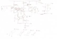
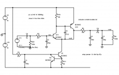
I've attached the schematic. The only issue I've had is that, without the 100nF capacitor across the output, I get a lot of hash, which is odd. So I suspect I'm getting some parasitic oscillations somehow. Perhaps I need to add some very local decoupling capacitors to the circuit. Despite the knowledge of potential oscillation, albeit filtered out, it sounds great!
I wanted to attach some pictures, but I've just realised they are too big to post, so the schematic will have to do for today.
Next, I want to build an input select (I have some reed relays kicking about), and a JLH headphone amp. It might get a bit tight finding all the bits for the headphone amp without spending anything, but I'll give it a go.
I'm certain this build isn't perfect. There have been some interesting compromises. But it's been great fun to do!
More pictures to follow.
Cheers,
Phil
Thought I'd share my latest meddlings.
Basically, I have been feeding my JLH 96 with a DAC via a passive pre. My passive pre has been either a linear 10k potentiometer, or a nice Alps 50k potentiometer. The linear is the right kind of impedance, but cannot be used quietly because of it's taper, and the 50k alps is lovely, but seemed to sound lifeless.
So, I thought I'd try and build an active buffer stage for my Alps pot, and call it a preamp 🙂
I set myself the rule that it needed to be done completely free of charge - using only bits I had lying around. Thankfully I did have some nice bits and bobs, although some bits are a bit overkill (120VA 15-0-15 toroid, 2x10,000uF 63v Cerafines), and some possibly not good enough (317/337).
The design is based on one of the Naim preamp schematics found on acoustica.org.uk (if you have a look at the Naim preamp tweaking page...). I used a similar design as a headphone amplifier years ago and wanted to see how it coped as a line level buffer.
I wanted to try a DC coupled B1 buffer, but thought it might be fun to try something with BJTs (and I have very few JFETs and loads of BC550s {and thankfully 2 BC560s!} - so able to keep the cost to zero).
I wasn't sure how much of a difference the circuit would make. Frankly, having listened to it for a while now, I am frankly gobsmacked! It sounds awesome. Suddenly, because the DAC is no longer struggling to drive the input of the amp (because the amp saw a much larger source impedance when I used a passive preamp) bass seems far more prominent, and detail in general drastically improved.
I've attached the schematic. The only issue I've had is that, without the 100nF capacitor across the output, I get a lot of hash, which is odd. So I suspect I'm getting some parasitic oscillations somehow. Perhaps I need to add some very local decoupling capacitors to the circuit. Despite the knowledge of potential oscillation, albeit filtered out, it sounds great!
I wanted to attach some pictures, but I've just realised they are too big to post, so the schematic will have to do for today.
Next, I want to build an input select (I have some reed relays kicking about), and a JLH headphone amp. It might get a bit tight finding all the bits for the headphone amp without spending anything, but I'll give it a go.
I'm certain this build isn't perfect. There have been some interesting compromises. But it's been great fun to do!
More pictures to follow.
Cheers,
Phil
Attachments
I"m guessing that you're oscillating. Maybe 100 pF from collector to base of your PNP output transistor would tame it. What do you think?
Yes, I was suspecting something like that, but unsure as to where to look. I think I have something similar in size. I'll give it a try. Thanks for the suggestion.
I'll also try and downsize my photos of it 🙂
I'll also try and downsize my photos of it 🙂
Hi Godfrey,
It's 100nF. I thought with the 300 ohms, it forms a 1st order low pass filter with a 3dB point of about 33kHz.
Sounds as if it's reproducing the highs okay to me. Cymbals sound great. But I'll look into that.
Besides, it's not ideal having it there. Wasn't intended. I had to add it to filter out some peculiar noise.
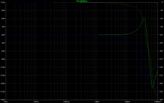
I did a quick sim...I shows the peaking I expected, indicative of problems with oscillation. Pictures show response with compensation cap Cc at 0 pF (green) and 47 pf (blue). Response plotted is from input base (bin) to output collector (cout). You can probably remove the 100 nF on the right side of the 300 Ohm resistor.
Attachments
Last edited:
Wow!
Thanks for that. I've been trying to simulate this, but found the latest Eagle (which I've used in the past) doesn't have a simulator (or I couldn't find it at least!). I shall have a go next week. I agree, I would like to lose the 100nF.
Once I've resized the photos so they're small enough files for the site, I'll post them.
Thanks again!
Hi Phil - Glad you're still playing!
Other things to try which may not appear related , but might help baseline quality:
1) Try splitting the 47K resistor into 22K+22K with the 100uF cap to 0v from the junction of the two resistors. It will make the Q1/Q2 CCS quieter and more stable. If you want to add to that, a small resistor in the collector of Q1 (say 100R) stops the output CFP 'seeing' an capacitative load in the CCS. This can help HF happiness.
2) djoffe has posted on compensation caps for the Sziklai output, well worth experimenting with. But an alternative approach is to intrinsically damp things by adding a small resistor in the base connection of Q13. Try, say, 47ohms or 100R or even 220R; it can be enough to attack the same root cause at source.
That 33oR/0.1uF output filter is currently a bandaid at best - shouldn't be needed. If you're still nearby please pop over for coffee and the o'scope!
Best
Martin
Hi Martin,
Good to hear from you! In fact, the output caps were once yours (this really is a project where I'm determined to reuse old parts 🙂 ).
Yes I am still nearby. Meeting up sounds like a plan some day. I have a JLH worth a listen to as well.
I see what you mean about the base resistor. That's what I tried with the input NPN. The base resistor there was originally 820 ohms - hoping to stall any oscillations, and after comparing to the Naim schematic, decided to up it to 2.7k (which I had to hand). Seemed to improve things a bit, but not as much as the bandaid.
Thanks to all for the tweak suggestions. I shall have a play this week (and I'll downsize some photos too!).
Phil
Don't you just hate it when you've written a whole reply, then your wireless drops out, and when it's finally sorted, you have to rewrite it!?
Here's some resized photos. Rubbish, because I used my phone. One day, I'll use a real camera and post a gallery of all my heath-robinson-esque kit.
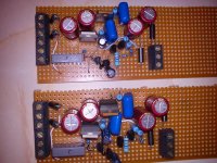
So, first a photo of the buffers being made. I wasn't sure how long they'd be, so I cut them to length afterwards.
Then a shot of them loosely in place, using the PSU just to get it working. Recognise those tants Martin?😀
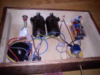
Then, mounted in situ. Much neater now, but I will dismantle them later in the week to try to stifle that oscillation.
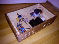
And, a shot from the back. There are extra holes for more connections. I hope to add an input select when I finally get round to it.
The toroid, and reservoir caps are possibly overkill (although very lovely to have - nice and heavy too), but I had them to hand, and had little else use for them, so could justify their use.
The case is an old plywood shipping crate that was thrown out by my old employer. A bit of sanding and some danish oil, and voila, perhaps no longer some old shipping crate - ok maybe not.
And, of course the lovely Alps pot, niftily fixed with a spare cable tie - no expense spared.
Here's some resized photos. Rubbish, because I used my phone. One day, I'll use a real camera and post a gallery of all my heath-robinson-esque kit.
So, first a photo of the buffers being made. I wasn't sure how long they'd be, so I cut them to length afterwards.
Then a shot of them loosely in place, using the PSU just to get it working. Recognise those tants Martin?😀
Then, mounted in situ. Much neater now, but I will dismantle them later in the week to try to stifle that oscillation.
And, a shot from the back. There are extra holes for more connections. I hope to add an input select when I finally get round to it.
The toroid, and reservoir caps are possibly overkill (although very lovely to have - nice and heavy too), but I had them to hand, and had little else use for them, so could justify their use.
The case is an old plywood shipping crate that was thrown out by my old employer. A bit of sanding and some danish oil, and voila, perhaps no longer some old shipping crate - ok maybe not.
And, of course the lovely Alps pot, niftily fixed with a spare cable tie - no expense spared.
Attachments
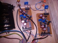
Oh yeah, the buffer circuit, as you look at it in the first photo, is sort of upside down. Enjoy 🙂
And I know the toroid wiring is a mess - I haven't cut it's wires yet and tidied up.
And I know the toroid wiring is a mess - I haven't cut it's wires yet and tidied up.
Thanks for the suggestion.
I think they might all be a bit tricky - as I stupidly tried to make the circuits as small as possible, but I shall have a play.
I think they might all be a bit tricky - as I stupidly tried to make the circuits as small as possible, but I shall have a play.
Well, I thought I'd initially try the 100pF between the base and collector of the PNP - mainly because I had 100pF, and it was easier than trying to sneak a resistor between the two transistors - and it worked a treat! The noise has gone, and I no longer need the 100nF across the output.
So, thanks for all the suggestions, and sorry I didn't get to try them all.
It's odd, because I built a headphone amp using a very similar circuit which didn't exhibit this oscillation (and I have been testing this at times with headphones - due to laziness). I suspect its related to resistor value differences (as hinted at by Martin).
Next, I want to knock up a input selector. I have some reed relays and TTL chips/transistors that should be suitable. I'll do an update when I've knocked something up.
Thanks for the help!
Phil
Brief update. I've been working on input selection. As I have a few momentary switches and I didn't have the right TTL logic to hand, I've lashed up a few S-R latches and some diode logic (basically a few 3-input OR gates) to drive some reed relays I have for input selection. I often feel that, for specific tasks, you can make more compact circuitry with a few discretes. I think this circuit wouldn't have been much smaller with standard ICs.
Works well (it didn't without the diodes - they were an afterthought as the photo will later demonstrate 🙂 ). I shall post a schematic and pictures when it's working with the relays.
Works well (it didn't without the diodes - they were an afterthought as the photo will later demonstrate 🙂 ). I shall post a schematic and pictures when it's working with the relays.
Here is the input selection schematic.
It works well, but I haven't tried it with switching real audio signals. I'll post some photos one day!
More on the buffer stage. I visited Martin last night, and we listened to his tweaked Naim CD player, this preamp (well the buffer), my JLH amp and his lovely Impulse horns. Not only was I very pleased with the JLH, but also pleased that the buffer was in the chain and it didn't really reveal itself as a limiting factor. Didn't seem to upset anything.
Very pleased with this project so far 😀
Attachments

Yup, sounded just lovely.
Put it this way - we just poured all sorts of music through Phil's amps for about 4hours just for pleasure, not once stopping to try to discuss what it all sounded like. And we'd have carried on rather longer except it was late 😀
Thanks Phil!
Put it this way - we just poured all sorts of music through Phil's amps for about 4hours just for pleasure, not once stopping to try to discuss what it all sounded like. And we'd have carried on rather longer except it was late 😀
Thanks Phil!
- Status
- Not open for further replies.
- Home
- Amplifiers
- Solid State
- Spare bits preamp