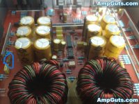
Does anyone know the value of the resistor that goes in the power supply?
1 end connects to the middle leg of the power supply fets the other end connects to a cap then to one of the windings on the transformer..
I believe its a 1 watt resistor but dont know the value since it burnt pretty bad
Its circled in this pic but cant make out the color bands
1 end connects to the middle leg of the power supply fets the other end connects to a cap then to one of the windings on the transformer..
I believe its a 1 watt resistor but dont know the value since it burnt pretty bad
Its circled in this pic but cant make out the color bands
Attachments
Last edited:
Looks like there are two power supplies and so I am taking a stab at the possibility that you will find a similar device on the second power supply opposite of the one that is circled that is burnt.
It also looks like a simple Zobel filter <RC network > and these typically have values between 4.7 and 10 ohms. And yes it appears to be a 1watt ceramic metal film resistor...Hope this helps some I don't have any info on this series of offshore amps
It also looks like a simple Zobel filter <RC network > and these typically have values between 4.7 and 10 ohms. And yes it appears to be a 1watt ceramic metal film resistor...Hope this helps some I don't have any info on this series of offshore amps
Last edited:
Thanks i found the other one but thats burnt also .. I can make out a few of the color bands
first color band either dark purple or black
Second color band white
3rd color band is either white or silver
4th band is gold
Any ideas what the value may be?
first color band either dark purple or black
Second color band white
3rd color band is either white or silver
4th band is gold
Any ideas what the value may be?
Closer i look at it it may be a 9 ohm resistor..
So im gonna try a 10 ohm resistor in the amp to see if it works
So im gonna try a 10 ohm resistor in the amp to see if it works
Ok i replaced the 2 resistors.
I removed the rectifiers from the amp..
I only have 1 fet per power supply right now..
Drivers check good..
As soon as i power it up the fets get red hot within 2 secs..
Do i need more them 1 fet per power supply to see if there is any other problems ?
Or should 1 work per supply for now ?
I removed the rectifiers from the amp..
I only have 1 fet per power supply right now..
Drivers check good..
As soon as i power it up the fets get red hot within 2 secs..
Do i need more them 1 fet per power supply to see if there is any other problems ?
Or should 1 work per supply for now ?
I put 2 fets per supply..
I put 10 ohm resistors in place of the burnt resistors that i could not make out the color bands..
I checked all power supply drivers and they all test good..
Within 3 secs all 4 of the fets get hot in both supply's ..
if thoose resistors arent the correct value would that cause the fets to heat up ?
Or what would i check next?
OK i found another amp here its a Kole audio and its very very close to this amp ..
The resistors are 22 ohms..
I guess ill recheck the drivers since both supplys have problems with the fets heating up within 2 secs..
The resistors are 22 ohms..
I guess ill recheck the drivers since both supplys have problems with the fets heating up within 2 secs..
Those look OK but that's unloaded and it could change when you install FETs.
If there are 2 supplies, there are 4 sets of gate resistors. Check the signal on all 4 sets.
If there are 2 supplies, there are 4 sets of gate resistors. Check the signal on all 4 sets.
Checked the signal on all sets it looks the same ...
Put 2 fets per supply back in within 3 secs they get red hot...
Any ideas where to look now?
Put 2 fets per supply back in within 3 secs they get red hot...
Any ideas where to look now?
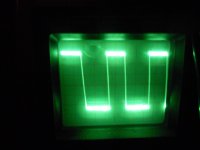
Remove the FETs. Connect a 1k resistor between the gate pad and the drain pad for one FET in each of the 4 banks. Does the gate signal still look square?
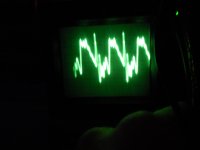
with the 1K resistors soldered in between the gate and drain..
The waveform is not square at all
The waveform is not square at all
Last edited:
That's not good.
Do you see a square wave on the output of the 494?
Do you see a square wave on the base of the PNP driver transistors?
Do you see a square wave on the emitter of the PNP driver transistors?
Do you see a square wave on the output of the 494?
Do you see a square wave on the base of the PNP driver transistors?
Do you see a square wave on the emitter of the PNP driver transistors?
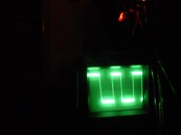
PIN13 appears to be the output I get the same waveform on pin 13 as i do on the gate pads..
ON the base and emitter of the A1266 drivers i get the same waveform as the 494 and the gate pad..
Waveform doesnt look good at all..
ON the base and emitter of the A1266 drivers i get the same waveform as the 494 and the gate pad..
Waveform doesnt look good at all..
- Status
- Not open for further replies.
- Home
- General Interest
- Car Audio
- Soundstream XTA 880.2