Another SS on my bench today. This amp works on the bench for the most part, but here are the previous repairs and also current issues:
Repairs
PS Fets
PS Caps are now XICON 2200uf16v
Right channel using mis-match TIP107 (ST and original mix)
Right channel TIP102 un-touched
Evidence of new driver boards
Q75 and Q76 were replaced or re-soldered using OE parts
Right channel MPSA14 under the board was badly soldered not even sure if all 3 legs were attached
Problems needing addressing
TIP107 in right channel mis-matched - Will replace with sequential ST brand units
ALL the switches sound like garbage and need replacement
At least the gain pots sound like nails on a chalkboard and need replacement
Both 10w snubbers need to be re-attached and secured
General condition of the amp guts is fair. Needs some cleaning and TLC
Again, the amp barely working and since the switches and gains need replacement I pulled the board (Thats when I found the TIP107 mismatch as well)
Question1: On the TIP107s in the right channel. Looks like the previous failure only required about half the TIP107 to be changed (Mismatching now) and did not take out any of the emitter resistors, but of course with the MPSA14 being replaced I'm just hesitant about anything in this area. Should I replace the emitter resistors when I change the TIP107s?
Question2: Should I replace the TIP102 + emitters in the right channel seeing as the TIP107 bank had issues?
Left channel no illnesses, however I know that for the past 10+ years this amp has been used as a sub amp in bridged more.
I'll post more issues as I find things out.
Last edited:
The premise for my post is; I wish t make this amp reliable for low impedance operation between 1.5~2ohms bridged. Me seeing the TIP107 mis-matched set prompted me to post here and dig a little deeper.
The emitter resistors are likely OK for the 102s but I'd check all of them very carefully. It will be somewhat difficult with a Fluke 10 (which is otherwise a great meter) alone. You could rig something up using a current limiting resistor to test them at higher resolution.
I'm using a Fluke 16 now actually. My Fluke 10 died on me 2 years ago. The 16 adds some min/max voltage features, cap reassurance, and some automation. I believe resistance is still the same as the Fluke10 though. I'll update my signature.
Last edited:
Using my Fluke 16, all emitter resisters are measuring 0.3ohms. Sometimes I see the meter flash about 0.2ohms if I wiggle the leads. I'm guessing all the emitters are OK then... which leads me to wonder how bad it would be to leave everything as-is except matching with just new TIP107 in that channel and leave the TIP102 side alone.
Replacing the 107s may be enough but I don't know what caused the channel to fail. I think I'd replace all of the outputs in that channel.
I don't know what caused the channel to previously fail either.
I know that this amp came off of a sub box that had a classic single Eclipse SW8200 12" sub with a 2000w rating... so this amp survived life with the mis-matched outputs, though possibly only at 4-ohms bridged load. Thats still a pretty beefy old subwoofer to live with and then tell the tale.
Thank you


Also the cap at C65 connected between the 3524 and the PS drivers is currently a 10v4.7uf cap. Its supposed to be 16v. Its also different brand and color(orange) which I've not seen before on SS1000 amps. Looks like all transistors and caps in the PS circuit have been replaced between the 3524 and the toroid. However, the gate resistors on the FETs look to have never been replaced even still they are measuring 3.3ohms. The amp is using 7050 FETs.
Since I ordered a pile of 16v4.7uf caps I'll swap out C65.
Since I ordered a pile of 16v4.7uf caps I'll swap out C65.
Last edited:
Reversed is likely correct. Check for pin-pin connection between that driver and the one on the driver board. At least some of them were installed wrong by the manufacturer.
So that seems to be an issue then across all 4 pairs of driver transistors. In each pair, the base of one is connected to the emitter of the other (Base-to-emitter) whereas on the schematic its base-to-base and emitter-to-emitter . Being a manufacturing error, Im surprised this worked out. I guess the mistake makes only one driver actually perform the work. I wonder if that could have caused output failures under high current.
So, I should reverse Q73, Q74, Q75, & Q76?
So, I should reverse Q73, Q74, Q75, & Q76?
The drivers should be in parallel (B-B, C-C and E-E through 49.9 ohm resistors). Correct any that are wrong.
Ok.
Next noticed the rectifier in D18 may was changed. Oem soundstream TO-220s usually have their legs slightly painted. This one did not. All rects are FE(P or N)16DT still, but this one seems to have a different date code or other numbers on its front. Picture attached. I know SS amps have a tendency to be weak in the area of rectifiers and so I may replace all 6x of these.

Next noticed the rectifier in D18 may was changed. Oem soundstream TO-220s usually have their legs slightly painted. This one did not. All rects are FE(P or N)16DT still, but this one seems to have a different date code or other numbers on its front. Picture attached. I know SS amps have a tendency to be weak in the area of rectifiers and so I may replace all 6x of these.
Last edited:
Was there a question.
Please post images as follows.
Go Advanced
Manage Attachments
Browse
Upload
Repeat as necessary
Preview post to see how the post will look.
Click Submit Reply to send it to the forum.
Please post images as follows.
Go Advanced
Manage Attachments
Browse
Upload
Repeat as necessary
Preview post to see how the post will look.
Click Submit Reply to send it to the forum.
I was using Tapatalk from my cellphone to post a few pictures including the picture in post #14. Unfortunately Tapatalk posts pictures as thumbnails. If you click on the thumbnail it will enlarge to full screen and perfect to read. It was just faster to post photos for me that way, but I understand the inconvenience of browser opening up another window. Sorry.
Should I replace the 6 rectifiers?
Should I replace the 6 rectifiers?
The rectifiers are in two groups of 3 parallel rectifiers. The 3 in parallel should match.
I don't know why SS has so many rectifier failures. I don't know if it's the old FEN and FEP parts but I've never seen a new part like the MUR1620CT and MUR1620CTR fail.
I'd replace all of them.
I don't know why SS has so many rectifier failures. I don't know if it's the old FEN and FEP parts but I've never seen a new part like the MUR1620CT and MUR1620CTR fail.
I'd replace all of them.
Thanks.
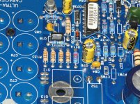
Looking back at C65 which has the wrong capacitor voltage rating (Orange cap in the thumbnail photo), there is also something going on with D738, D739, and R107. There is a J175 transistor legged between the pads of D739 and R107
C65 is wrong so its got me looking around this area.
D738 looks like its not an MBR150 per the schematic.
D739 is being subbed by this J175
The J175 is testing a little funny. I lifted leg 3 to test it and between legs 1 & 3 its measuring 58 ohms. Between legs 1&2, and then 3&2 its passing diode check.
Click the Thumbnail. Is anything weird or broken here?
Last edited:
In photos I have, I don't have the J175 but I've seen that in some SS amps.
The J175 JFET sounds normal. Read section 6 on the Checking Semiconductors page of the tutorial.
The J175 JFET sounds normal. Read section 6 on the Checking Semiconductors page of the tutorial.
- Home
- General Interest
- Car Audio
- Soundstream Reference 1000sx