Hi everyone,
So I recently bought this Reference 404s amp really cheap. After receiving the amp I tested it and found that the 3 and 4 channel made a loud humming noise so I decided to open it up to see if there was an issue that I could spot on visual inspection and I found that the soldering on the input terminals was damaged. I fixed that but to no avail. The humming soundn was still there. No is maybe a good moment to tell you that I have no (very, very little) knowledge on electronics but always eager to learn something and having lots of time at the moment I decided to dive in. Watching youtube video's, bought a book on electronics, a cheap chinese handheld oscilloscope and component tester, trying to read shematics etc. Unfortinately I might have blown the amp up on one of the first steps with power connected to the board by pulling the board over something metal on my desk (I know pretty stupid!). So that's where I am now. I will list here what I've done so far and hope to get some new directions from you on what to do next.
Shematics are also below.
So, the amp doesn't power up anymore. The red led doesn't come on.
On visual inspection nothing is burned and transistors don't look damaged.
Measuring all the transistors on the board they seem all fine.
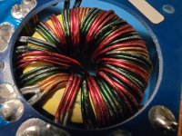
The transformer (T11 on the schematics) is (and was when I opened the amp) covered in solder on the bottom and the isolation is slightly damaged (see photo).
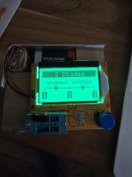
D20 and D7 "two diodes" seemed to short showing no resistance in which ever way I measured them however when I desoldered them and put them in my component tester it told me they're fine (see photo) so I put them back in.
Measuring the capacitors C37 and C36 in circuit the C36 capacitor measures 1000 uF and C37 doesn’t measure at all. Also there is no resistance between the + and – leads of the cap. Thinking the cap might be the problem I took it out but when I measured it out of the board there’s nothing wrong with it.
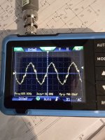
After putting it back in I decided to hook up the power supply again (12v max. 500mA). Nothing gets really hot fast but voltage drops to 6v on the power supply. Hooking up the oscilloscope gives me the image shown in the photo below.
That’s about as far as I’ve gotten so far. I hope to hear if what I wrote points into a certain direction. Thanks.
So I recently bought this Reference 404s amp really cheap. After receiving the amp I tested it and found that the 3 and 4 channel made a loud humming noise so I decided to open it up to see if there was an issue that I could spot on visual inspection and I found that the soldering on the input terminals was damaged. I fixed that but to no avail. The humming soundn was still there. No is maybe a good moment to tell you that I have no (very, very little) knowledge on electronics but always eager to learn something and having lots of time at the moment I decided to dive in. Watching youtube video's, bought a book on electronics, a cheap chinese handheld oscilloscope and component tester, trying to read shematics etc. Unfortinately I might have blown the amp up on one of the first steps with power connected to the board by pulling the board over something metal on my desk (I know pretty stupid!). So that's where I am now. I will list here what I've done so far and hope to get some new directions from you on what to do next.
Shematics are also below.
So, the amp doesn't power up anymore. The red led doesn't come on.
On visual inspection nothing is burned and transistors don't look damaged.
Measuring all the transistors on the board they seem all fine.
The transformer (T11 on the schematics) is (and was when I opened the amp) covered in solder on the bottom and the isolation is slightly damaged (see photo).
D20 and D7 "two diodes" seemed to short showing no resistance in which ever way I measured them however when I desoldered them and put them in my component tester it told me they're fine (see photo) so I put them back in.
Measuring the capacitors C37 and C36 in circuit the C36 capacitor measures 1000 uF and C37 doesn’t measure at all. Also there is no resistance between the + and – leads of the cap. Thinking the cap might be the problem I took it out but when I measured it out of the board there’s nothing wrong with it.
After putting it back in I decided to hook up the power supply again (12v max. 500mA). Nothing gets really hot fast but voltage drops to 6v on the power supply. Hooking up the oscilloscope gives me the image shown in the photo below.
That’s about as far as I’ve gotten so far. I hope to hear if what I wrote points into a certain direction. Thanks.
Attachments
Initially, did channels 1 and 2 play normally?
On that 12v, 500ma power supply?
By 'no resistance' do you mean 0.000 ohms or do you mean infinite resistance? In the future, when you measure something with the meter, post the exact reading displayed on the meter.
On that 12v, 500ma power supply?
By 'no resistance' do you mean 0.000 ohms or do you mean infinite resistance? In the future, when you measure something with the meter, post the exact reading displayed on the meter.
Hi Perry,
Yes, channels 1 and 2 were fine.
I initially used a 7A laptop power supply before switching to a bench top power supply. I'm kind of hesitant to use more amps with none of the MOSFETs mounted on the heatsink.
My multimeter switches between 0.0 and 0.1 ohms.
Yes, channels 1 and 2 were fine.
I initially used a 7A laptop power supply before switching to a bench top power supply. I'm kind of hesitant to use more amps with none of the MOSFETs mounted on the heatsink.
My multimeter switches between 0.0 and 0.1 ohms.
Too much current limiting has caused endless problems. If you're going to do this sort of work, you have to be attentive and know what's going on at all times. Clamp the amp back down to the heatsink or closely monitor the temperature of the transistors when you have power applied.
My absolute favorite (as far as I know, no one uses it) is a 2 ohm current limiting resistor in the B+ line with a 12v buzzer connected across the resistor. The buzzer (when working as it should) gives you an audible indication of the current flow into the amplifier. Typically, it's just a barely audible sound but when the current starts to increase, the sound gets louder, alerting you to a problem. The 2 ohm resistor needs to be rated for at least 50w and I'd recommend the cylindrical wirewound types. Attached or similar.
0.0 ohms across the capacitor pads?
Was the humming present with no input signal or only when an input signal was connected?
Attachments
I'll see if I can get my hands on one of those resistors. By connecting a buzzer across the resistor you mean in parallel?

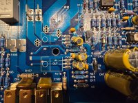
Photo is measurement of the C37 cap. Positive lead of the multimeter on the negative pole of the capacitor.
The humming was present with nothing but a speaker connected to the output and increased when I would touch any of the components on the board.
Photo is measurement of the C37 cap. Positive lead of the multimeter on the negative pole of the capacitor.
The humming was present with nothing but a speaker connected to the output and increased when I would touch any of the components on the board.
Yes, parallel. If you try this, the buzzer I use is the one attached (to allow you to find something similar). The one I have is too loud so all but a small part of the opening in it is covered with adhesive tape.
https://www.digikey.com/en/products/detail/same-sky-formerly-cui-devices/CEP-2242/412374
https://www.sameskydevices.com/product/resource/cep-2242.pdf
Does C36 read the same as C37?
What happens if you reverse the probes? Same reading?
https://www.digikey.com/en/products/detail/same-sky-formerly-cui-devices/CEP-2242/412374
https://www.sameskydevices.com/product/resource/cep-2242.pdf
Does C36 read the same as C37?
What happens if you reverse the probes? Same reading?
Reversing the probes doesn't make a difference on C37.
C36 measures 39.6 KOhm and reversing the probes it's 5.95 MOhm.
C36 measures 39.6 KOhm and reversing the probes it's 5.95 MOhm.
Do you mean U6 the LM317 voltage regulator?
There seems to be a discrepancy between the schematics and my board. U6 is U7 on the board and U7 is U9 on my board. U6 on my board is one of the TL072 op amps.
Also I'm not quite sure how to measure it. In diode mode or continuity
There seems to be a discrepancy between the schematics and my board. U6 is U7 on the board and U7 is U9 on my board. U6 on my board is one of the TL072 op amps.
Also I'm not quite sure how to measure it. In diode mode or continuity
Attachments
The positive regulator.
Looking at your photo, it's likely C42 that will show as shorted. If so, you need to pull it to eliminate it as a possible short.
Looking at your photo, it's likely C42 that will show as shorted. If so, you need to pull it to eliminate it as a possible short.
I took out the positive voltage regulator and it was okay.
Capacitor c42 I also took out and it was also good but I broke it taking the thing out so had to replace it. What made you suspect it being shorted?
Yesterday I was looking at another thread on a bad power supply of an R404s and thought I’d redo some measurements and actually write them down this time.
I can’t make any sense of it though. I measured the driver transistors, regulators, and rectifiers all with my multimeter on diode mode measuring between pins 1 - 2, 1 - 3 and 2 - 3
Driver transistors 2SA1562
Q2:
1-2: 0.789 v (started at 0.2xx V. and gradually climbed to this)
1-3: 0.644 v
2-3: 0.645 v
Q9:
1-2: 0.791 v (started at 0.2xx V. and gradually climbed to this)
1-3: 0.645 v
2-3: 0.645 v
Driver transistors 2N2222A
Q1:
1-2: 0.624 v
1-3: 0.993 v (numbers climbing up to this value)
2-3: 0.610 v
Q10
1-2: 0.623 v
1-3: 0.994 v (numbers climbing up to this value)
2-3: 0.613 v
Regulators
LM317 positive regulator:
1-2: 0.519 v
1-3: 0.954 v
2-3: 0.554 v
LM337 negative regulator:
1-2: 1.338 v (numbers climbing up to this value)
1-3: 0.586 v
2-3: 0.553 v
Rectifiers
FEP16DT
D7:
1-2: 0.000 v
1-3: 0.000 v
2-3: 0.000 v
(multimeter beeps continuously)
D20:
1-2: 0.000 v
1-3: 0.000 v
2-3: 0.000 v
(multimeter beeps continuously)
FEN16DT
D18:
1-2: 2.291 v (numbers climbing up to this value)
1-3: 0.000 v (continuous beeping)
2-3: 0.419 v
D19:
1-2: 2.290 v (numbers climbing up to this value)
1-3: 0.000 v (continuous beeping)
2-3: 0.419 v
Why are some of the measurements going up while measuring? Is this because of capacitors charging?
The 0.1 ohm reading means that something is shorted. I suspected that it was after the rectifiers since the amp wasn't completely shut down but now it appears that you could have a shorted positive rectifier. The steady beep from 1-3 is normal and is reading across the secondary transformer windings. The readings on the FEP rectifiers tends to indicate that one is shorted.
Finally some progress. You were right about the FEP rectifier. I had replaced one a couple of weeks ago and luckily ordered a spare one as well that I used to now replace the other one and the amp powers up again!!
I'll screw it back on the heatsink tomorrow to test it.
And then there's that humming sound on channels 3 and 4.
I'll screw it back on the heatsink tomorrow to test it.
And then there's that humming sound on channels 3 and 4.
So I tested the amp and its working. Channels 1 and 2 are good. No humming, no noise. Channels 3 and 4 however still sound awful. I found that this only occurs when using the ch. 3 and 4 inputs though. Using the channel 1 and 2 inputs over the ch. 3 and 4 amps also sounds good. Therefore to me it seems the problem must lie between the inputs and the local/remote switch. Am I right?

I read somewhere that these switches are notoriously problematic. Does it make sense to remove it and make a temporary connection to test it or do you have a better solution?
I read somewhere that these switches are notoriously problematic. Does it make sense to remove it and make a temporary connection to test it or do you have a better solution?
'Sounds awful' isn't very specific.
Can you see the distortion on the speaker output if you drive a sine wave into the amp?
If so, do you see that same distortion on the output terminals of any of the op-amps in channels 3/4?
The switches are awful, possibly only second to the COMAX switches in the JL amplifiers. They are in short supply. I haven't looked for identical replacements. Someone may have definitive good subs. I typically clean them if they are defective. Sometimes contact cleaner will suffice. Other times, they have to be disassembled and physically cleaned.
If the switch appears to be the problem, jumping the terminals is a good test. Generally, if the switch is the problem, the problem is intermittent and can be affected by moving the switch actuator slightly.
So, apparently the humming was just a ground loop when using my hifi streamer as a source (is there a logical explanation that this only occurs on channels 3 and 4?)
When connected to the jack of an old phone there was no humming anymore!
Thanks a lot for helping me out!
When connected to the jack of an old phone there was no humming anymore!
Thanks a lot for helping me out!
Resistance from the RCA shield to the non-bridging speaker terminal of the same channel (with no other connections [RCAs. power, ground, remote] to the amplifier)?
Check for all channels.
Check for all channels.
- Home
- General Interest
- Car Audio
- Soundstream amp not powering up.