Sorry couldn't decide which forum to put this in. If its wrong please move it.
I am currently building up a sound to light converter.
Circuit is courtesy of Maplin.
It uses an electret microphone.
That goes into an op amp that has gain.
The next stage is another op amp stage with variable gain controlled by a potentiometer.
The sound is then split into three channels low, mid and high.
Each channel has a volume control to set the light on level.
There are 3 opto-isolators between the sound channels and the triacs.
An externally hosted image should be here but it was not working when we last tested it.
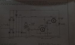
I first saw a "light organ" cct in a 1971 Elcom transistor replacement manual. (one of the books I learned from)
It was audio transformer isolated from the three SCR's.
Found it.
It was audio transformer isolated from the three SCR's.
Found it.
Attachments
Last edited:
We always called those "color organs", similar to what DUG said.
They were a popular project in electronics hobby magazines in the 1960s and 1970s. Still fun to play with.
They were a popular project in electronics hobby magazines in the 1960s and 1970s. Still fun to play with.
I used to manufacture single channel sound to light units back in 1968. There was an issue acquiring Triacs so a BT106, (from a Philips G6 chassis) and a bridge rectifier to use both positive and negative parts of the mains cycle and give full brightness to a coloured bulb in a PAR can, (empty 1/2 gallon bean tin with a socket in it). The thyristor was triggered with a 600R to 600R Post Office Telephone matching transformer and isolated the mains from the input.
I progressed to a three channel as described by Nigel and the opto isolators were zero crossing devices allowing inductive loads and stopped interference. I used to combine them with sequencers and sold them through Living Light Design Ltd, Maplin and direct to Amusement Arcades. The five channel sequencer spelt out B I N G O , corny or what!
I progressed to a three channel as described by Nigel and the opto isolators were zero crossing devices allowing inductive loads and stopped interference. I used to combine them with sequencers and sold them through Living Light Design Ltd, Maplin and direct to Amusement Arcades. The five channel sequencer spelt out B I N G O , corny or what!
We built many back in the 'disco days' 😀
One of the most effective was a single channel one, which I think came from Practical Electronics?.
It used the usual isolation transformer from the speaker and simple low-pass filtering, but then had a monostable feeding the triac - which gave a nice solid flashing to the beat.
The clever bit though was that it used three bulbs, two in parallel fed from the triac as normal, with the third ACROSS the triac. So the one across the triac was normally lit, and went out when the triac fired and the other two lit up. With the three bulbs in a row, and the centre one normally ON, it gave a very pleasing and simple effect.
- Status
- Not open for further replies.