Hi all, my first query here and a little background so you're aware of my knowledge (clue: next to nothing).
I want to build a decent amplifier at some point and have no background at all in electronics so I bought a basic electronics book, soldering station etc and have started to work my way through the basics. I've also bought a few cheap amps from China to practice my soldering technique rather than just playing with breadboards as ultimately I'm only interested in audio. These have worked fine but I have a problem with my latest purchase.
The kit is a TDA2030A stereo setup with tone controls. I have it wired to a bench supply feeding 12V as stated in the sheet (no instructions or data, just a schematic). The speakers are little JVCs rated at 10W into 6ohms. The source is my phone into a 3.5mm audio jack. After music playing nicely for about 20 seconds the LED fades and the music quietens and distorts. If I turn it off and then on again, the process of distortion repeats after a time interval.
Any insights gratefully appreciated.
Cheers
Neal
Welcome to diyAudio 🙂
It would help to know a bit more about the amp tbh. 12 volts sounds very low and is I believe the absolute minimum the chip is specified for.
What is the LED for ? Is it simply wired across the power supply as a power on indicator.
Could the problem be your supply not having sufficient current ability. You need to confirm the 12 volts is still present when the fault occurs.
Does the chip get hot ? I'm assuming its on a heatsink.
Could it be that your supply overheats and shuts down? Do you have a multimeter that can measure the incoming voltage? Measure before and after the issue occurs.
Are you using a heat sink with the TDA2030? If not, it could be the IC overheating.
According to the data sheet, the TDA2030 should be able to run on ±6 V (or +12 V).
If you post a build picture and a schematic it will be much easier to help you.
Tom
Are you using a heat sink with the TDA2030? If not, it could be the IC overheating.
According to the data sheet, the TDA2030 should be able to run on ±6 V (or +12 V).
If you post a build picture and a schematic it will be much easier to help you.
Tom
Last edited:
Hi Mooly,
Thank you for your 2nd welcome 🙂
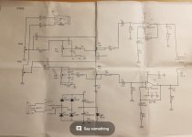
Image of schematic attached, hopefully!
Same results at 16V.
LED is for power on indication as you suggest.
Chips are on heatsinks with thermal paste and don't get hot.
Power supply is Tenma 72-10480 0-30V 3A just bought from CPC.
Voltage stays constant when distortion kicks in.
Tom, I don't think there's a problem with the power supply.
Cheers
Neal
Thank you for your 2nd welcome 🙂
Image of schematic attached, hopefully!
Same results at 16V.
LED is for power on indication as you suggest.
Chips are on heatsinks with thermal paste and don't get hot.
Power supply is Tenma 72-10480 0-30V 3A just bought from CPC.
Voltage stays constant when distortion kicks in.
Tom, I don't think there's a problem with the power supply.
Cheers
Neal
An externally hosted image should be here but it was not working when we last tested it.
If the...
...why does the LED fade?NealJ said:Voltage stays constant
An externally hosted image should be here but it was not working when we last tested it.
Right...
This runs on a split supply meaning there is an equal positive and negative rail. Do you see the plus and minus markings on the 17 volt points on the TDA2030.
The '12 volts' is actually meant to be an AC voltage from a transformer, but more than that it is a 12-0-12 or dual winding transformer.
12 volts AC will give around 17 volts DC after rectification. So the supply this amplifier runs on is plus 17 volts and minus 17 volts. A total of 34 volts DC but with the all important 0 volt 'in the middle'.
So the bad news is that this will not work on a single rail supply. Not what you wanted to hear 🙁
If the...
...why does the LED fade?
Because the single rail supply isn't a valid state and so the LED will be running through and 'charging' some of the caps. When the caps are charged via the LED current then the LED goes out.
I have an idea you can try.
I'm assuming you are feeding your 12 volts into the pins marked 1 and 3 on the power connector.
If you connect a 1k resistor across each of the power supply caps, thats those big 2200uF ones in the power supply, then you might pursuade it to play at low volumes.
The resistors MUST be equal values but absolute value isn't that critical. Don't go to low or they will get hot.
I'm thinking on the hoof here... try it 😉
Hi Mooly,
Thanks for your help. I'm not quite sure what you mean by single rail and 12 -0- 12 but I will do some reading! I don't mind things going wrong, it serves to help learning.
I will give your resistor idea a try and report back. Again many thanks for your help, it's much appreciated.
Thanks for your help. I'm not quite sure what you mean by single rail and 12 -0- 12 but I will do some reading! I don't mind things going wrong, it serves to help learning.
I will give your resistor idea a try and report back. Again many thanks for your help, it's much appreciated.
A single rail amp is as it says, it runs on a single supply voltage and crucially the speaker would be connected via a capacitor to block DC current from passing through the speaker. The output of the amp would be biased to be at one half the supply voltage and so allowing the amp output to move to higher and lower voltages between the fixed single supply rail.
The dual rail supply allows us to build what we call a 'direct coupled' amplifier (such as yours). Now the speaker connects directly from amp to ground with no cap. The DC voltage at the amp output is zero volts. The amp output can swing from zero up to the positive rail, and from zero to the negative rail. No coupling cap needed.
Looking at opamp theory might help you understand how this all works.
Another way to imagine the power supply is to think of batteries.
A 12 volt battery is just that, 12 volts.
Now lets connect two 6 volt batteries in series and what do we get ? We get an equivalent 12 volt battery but crucially we have available the centre point. If we call that 'ground' or 'zero volts' and connect our voltmeter to this point, then we would read PLUS 6 volts to the 'top' battery and MINUS 6 volts to the lower one.
That is a split or dual rail supply.
Thanks for the lesson. I get the battery illustration and I will have a read about opamps.
On a side note, is there a book recommended for beginners on audio electronics?
On a side note, is there a book recommended for beginners on audio electronics?
Books... hmmm.
I suppose 'The Art of Electronics' by Horowitz and Hill is a standard classic but mega expensive.
There is so much good information and references on line these days.
This is free from Texas Instruments. Lots of useful info:
https://www.ti.com/seclit/sl/slyw038b/slyw038b.pdf
I suppose 'The Art of Electronics' by Horowitz and Hill is a standard classic but mega expensive.
There is so much good information and references on line these days.
This is free from Texas Instruments. Lots of useful info:
https://www.ti.com/seclit/sl/slyw038b/slyw038b.pdf
Look at the schematic. J4 should have AC +/- 12V connected. Two secondaries or a center taped transformer. This will give you a +17V, 0V and a -17V. It helps to know that GND really means 0V.
According to the schematic, you need to use a 12-0-12 VAC transformer. So get a transformer that either has that configuration (commonly called 24 VCT (volt centre-tapped)) or two 12 V windings (which you then connect in series to form 12-0-12).
A transformer like the Hammond 1182M12 or 1182P12 would work well. Mouser carries the Hammond product line and will gladly ship to you.
Tom
A transformer like the Hammond 1182M12 or 1182P12 would work well. Mouser carries the Hammond product line and will gladly ship to you.
Tom
Mark, I never noticed (obviously). I sort of presumed all these dirt cheap amp kits ran off DC. I know now to study the schematics carefully. Every mistake teaches a lesson though!
Tom, thanks for the suggestion on the transformer. I don't think I'd purchase one just for this amp, it was only meant to be a little practice at soldering and having a working product at the end. I'm going to have a play with some of the small headphone amps now so that I can hopefully gain some knowledge to go with the construction.
Many thanks for everyone's input, this forum is certainly an excellent friendly, helpful resource, glad I came across it.
Cheers
Neal
- Status
- Not open for further replies.
- Home
- Amplifiers
- Chip Amps
- Sound distorts after 20 seconds.