Hello all,
I recently obtained a xm-7557 I was under the impression was functional, only for the front left channel to be non-functional.
Started with probing all psu transistors in circuit, no shorting or open circuit as far as I can tell.
All four large rectifiers passed current the proper way..
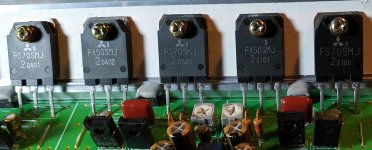
Probed all output Mosfets in circuit, no shorting or open circuits. I did however notice neither of those chips looked exactly like the others. See photo at the end. (The legs seemed off, the fonts were different, and one was missing the Mitsubishi logo all together.)
Using regulated 12.17[v] psu, I went ahead and blindly powered it up. I saw it "stably" powered up when I purchased it. No avalanche failure during those 20min.
Main rail voltage pairs, measured W.R.T. their ground, then between grounds
Rail set (A): -28.3, +28.3[V]
Rail set (B): -27.2, +28.0[V]
gnd-gnd: 2.1[mV]
UNDER NO LOAD
Attempt number one: Check bias of all transistors. although 12.17[V] psu was used, bias was checked. None were out of service manual's 1.2[mV] recomendation, EXCEPT front left! couldn't get a mili volt out of the sucker...
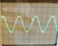
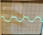
Swear I heard audio out of it when purchased, so I put some 1kHz through it and threw the silly scope on the speaker terminals to see if what it would look like. The photo at the bottom that looks good is identical to all channels, the one that looks horrible.. its channel FL again.
As I am relatively new to amplifier repair, I would appreciate some input here. Can I assume the following based on this data:
1. The power supply is likely okay
2. From the photo of the outputs, the FL channel (the two furthest right devices) have been changed at some point.
3. From research, the output devices, FS70SMj and FX50SMj are hard to find, therefore these are likely counterfeits.
4. Imbalanced components in the output section can cause distortion.
5. The wave form produced looks like clipping, but I have not seen clipping that the "Plateau" droops with time.
I am less sure of these:
6. The likely counterfeit components could be causing the inability to bias. (seems logical, but I don't have a clear Reason)
7. No voltage across TP6 and TP7 (bias locations for FL) could mean a short.
8. The droop in the waveform plateau could mean the power supply is sagging with the load, weak cap? I didn't have enough hands last weekend to measure the rails while outputting signal.
9. Am I missing something?
I hope this post is not too long winded. I wanted to hopefully cover some ground in a format I have seen on other help posts. I am also trying to check my logic in this post, if you see any assumption that I have made that is incorrect, please let me know.
Thanks,
Ian 🙂
I recently obtained a xm-7557 I was under the impression was functional, only for the front left channel to be non-functional.
Started with probing all psu transistors in circuit, no shorting or open circuit as far as I can tell.
All four large rectifiers passed current the proper way..
Probed all output Mosfets in circuit, no shorting or open circuits. I did however notice neither of those chips looked exactly like the others. See photo at the end. (The legs seemed off, the fonts were different, and one was missing the Mitsubishi logo all together.)
An externally hosted image should be here but it was not working when we last tested it.
Using regulated 12.17[v] psu, I went ahead and blindly powered it up. I saw it "stably" powered up when I purchased it. No avalanche failure during those 20min.
Main rail voltage pairs, measured W.R.T. their ground, then between grounds
Rail set (A): -28.3, +28.3[V]
Rail set (B): -27.2, +28.0[V]
gnd-gnd: 2.1[mV]
UNDER NO LOAD
Attempt number one: Check bias of all transistors. although 12.17[V] psu was used, bias was checked. None were out of service manual's 1.2[mV] recomendation, EXCEPT front left! couldn't get a mili volt out of the sucker...
Swear I heard audio out of it when purchased, so I put some 1kHz through it and threw the silly scope on the speaker terminals to see if what it would look like. The photo at the bottom that looks good is identical to all channels, the one that looks horrible.. its channel FL again.
An externally hosted image should be here but it was not working when we last tested it.
An externally hosted image should be here but it was not working when we last tested it.
As I am relatively new to amplifier repair, I would appreciate some input here. Can I assume the following based on this data:
1. The power supply is likely okay
2. From the photo of the outputs, the FL channel (the two furthest right devices) have been changed at some point.
3. From research, the output devices, FS70SMj and FX50SMj are hard to find, therefore these are likely counterfeits.
4. Imbalanced components in the output section can cause distortion.
5. The wave form produced looks like clipping, but I have not seen clipping that the "Plateau" droops with time.
I am less sure of these:
6. The likely counterfeit components could be causing the inability to bias. (seems logical, but I don't have a clear Reason)
7. No voltage across TP6 and TP7 (bias locations for FL) could mean a short.
8. The droop in the waveform plateau could mean the power supply is sagging with the load, weak cap? I didn't have enough hands last weekend to measure the rails while outputting signal.
9. Am I missing something?
I hope this post is not too long winded. I wanted to hopefully cover some ground in a format I have seen on other help posts. I am also trying to check my logic in this post, if you see any assumption that I have made that is incorrect, please let me know.
Thanks,
Ian 🙂
Last edited:
To upload photos click the following:
Go Advanced
Manage Attachments
Browse
Upload
Repeat as necessary
Preview post to see how the post will look.
Click Submit Reply to send it to the forum.
Go Advanced
Manage Attachments
Browse
Upload
Repeat as necessary
Preview post to see how the post will look.
Click Submit Reply to send it to the forum.
The Photos in this post are for the first post.
The photo of MOSFETs are lit to show the lettering and leg details.
The photo of a clean signal represents what the FR, RL, RR, and subwoofer channels produce. This exact photo is of the FR channel at identical gain, input voltage and scale of the FL channel.
The photo of a clipped, distorted signal are the output from the FL channel. identical. It makes me think I should monitor rail voltage at the legs...
For Both traces, Vertical: 0.5[V/div] Horiz: 0.5[msec/div]
Attachments
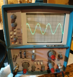
5000 series tek scope?
The rail voltage may be an issue but the fact that the top isn't clipped squarely could mean that the problem is a weak drive signal or even preamp level problems.
The rail voltage may be an issue but the fact that the top isn't clipped squarely could mean that the problem is a weak drive signal or even preamp level problems.
5000 series tek scope?
The rail voltage may be an issue but the fact that the top isn't clipped squarely could mean that the problem is a weak drive signal or even preamp level problems.
the scope is Tek, but it is a T912 hoover style. Its a relatively new addition to this addiction 😎. I had it apart last week and forgot to put the blue display shield back in place. Let me upload the un-cropped photo...
I will just keep working my way back from the current stage gates and see how life treats me. I will begin with Q104,5 and work my way back to IC703.
I will try and correlate the probe results given in Schematic 5-7 of the service manual with the known good channels in order to make up for the 2.2[V] difference between my psu and the recommended input voltage.
I have seen a guy on youtube, Bigclive.com, that always blows schematics up on a piece of 8.5x11 and writes on them. That gave me the idea to take the more easily read PCB diagram and toss on the ideal probe numbers from the block diagrams on Schematic 5-7... Anyone care to share their favorite method or taking probe measurements? (look up bigclive.com, I think he is hilarious)
Attachments
I have one of those. It's in great condition but something in the PS failed. It's a good scope.
You don't need to print anything. PDF XChange Viewer allows you to make notes and draw on the diagrams. Save it as a different name (add NOTES to the ens of the file name so it will be sorted with the original) and mark it up as you wish.
You don't need to print anything. PDF XChange Viewer allows you to make notes and draw on the diagrams. Save it as a different name (add NOTES to the ens of the file name so it will be sorted with the original) and mark it up as you wish.
Perry,
My scope has some issues in the PSU as well, it has some low voltage issue(according to the service issue). Makes the power indicator blink rapidly for a minute or two while the scope powers on and off a couple times.
In all honesty, it is my first and only as I am still in school, money is tight... But I can get a clean wave after awhile 😀
That may be capacitors that need to be re-formed (their internal insulation). It may improve with use.
If not, there is a forum for Tek scopes (TekScopes@groups.io | Home) that helps with vintage Tek equipment. I don't know if the 912 is vintage enough. If not, they may be able to point you to someone who can help.
If not, there is a forum for Tek scopes (TekScopes@groups.io | Home) that helps with vintage Tek equipment. I don't know if the 912 is vintage enough. If not, they may be able to point you to someone who can help.
That may be capacitors that need to be re-formed (their internal insulation). It may improve with use.
If not, there is a forum for Tek scopes (TekScopes@groups.io | Home) that helps with vintage Tek equipment. I don't know if the 912 is vintage enough. If not, they may be able to point you to someone who can help.
I seem to recall hearing "reforming" caps in a video once. But yes it does like some time to wake up. I may have to go into that forum if the silly scope doesn't stay silly.
I will get back to the Sony when I have time this weekend.
Thanks Perry,
And thanks to this forum
- Status
- Not open for further replies.
- Home
- General Interest
- Car Audio
- Sony XM-7557