This is a simple tweaking that I did on my cheap Sony CD/SACD/Blu-ray transport.
As the original SMPS had an issue, I thought to improve a little the (quite good) quality of the player by removing the internal PSU and making an external low noise linear power supply.
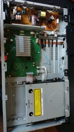
Original power supply unit had two 12Vdc sockets from a single rail, one filtered with a 10μH inductor.

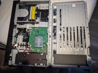
Iremoved the SMPS and used original wiring plus a GND cable.:

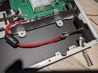
I enlarged the mains input hole to put a 2-pole mil socket where I soldered the new 10uH choke:


New linear PSU is a classic schematic with LT1084 and CRC at input:


Nothing special, but just a good upgrade over the very simple stock SMPS.
I also changed stock feet with neoprene ones that I had and put two wooden sides à la ES series and a little marble weight on top:


As the original SMPS had an issue, I thought to improve a little the (quite good) quality of the player by removing the internal PSU and making an external low noise linear power supply.
Original power supply unit had two 12Vdc sockets from a single rail, one filtered with a 10μH inductor.
Iremoved the SMPS and used original wiring plus a GND cable.:
I enlarged the mains input hole to put a 2-pole mil socket where I soldered the new 10uH choke:
New linear PSU is a classic schematic with LT1084 and CRC at input:
Nothing special, but just a good upgrade over the very simple stock SMPS.
I also changed stock feet with neoprene ones that I had and put two wooden sides à la ES series and a little marble weight on top:
Last edited:

I like what you did with the power supply. very nice.
I have this exact same player and it stopped working, I want to use an external power supply as well, not as good as yours, but a simple power supply that outputs 12V 2A or 3A, doesn't matter, and connect the (+12V) to the mainboard like you did, and the (-12v) to the GND, same as you did.
what is the importance of using the 10uH choke? can I connect the new power supply without it? or it is absolutely necessary?
Thank you
The original smps has a filtered line with 10uH choke and a non filtered one. Better to use a 3A smps and a small smps filter like that sold in Forum store
Thank you for your answer.
I eventually used a 2A smps and a ferrite core wound around it's wires and the device works OK. I thought of using a 3A smps but I was affraid that the little fuses on the motherboard could not handle this current.
I eventually used a 2A smps and a ferrite core wound around it's wires and the device works OK. I thought of using a 3A smps but I was affraid that the little fuses on the motherboard could not handle this current.
Hi guys, my player started to shut down by itself after few minutes. I have tried to reset to factory setting but still misbehaving. I am thinking of change the smps to linear one. Just to confirmed that your ground from DC side is mounted onto the board and the 2 of 12VDC lines is joined at the positive connector end?.
quan
quan
can I take out the original 10uH choke from the bad smps and use it? I have a problem getting a new one. and to which of the wires should I connect the choke to the white or to the gray?The original smps has a filtered line with 10uH choke and a non filtered one. Better to use a 3A smps and a small smps filter like that sold in Forum store
Thank you.
Exact. Original SMPS is connected to gnd only by chassis. Even an external SMPS works fine, especially if filteredHi guys, my player started to shut down by itself after few minutes. I have tried to reset to factory setting but still misbehaving. I am thinking of change the smps to linear one. Just to confirmed that your ground from DC side is mounted onto the board and the 2 of 12VDC lines is joined at the positive connector end?.
quan


I would love to do this to my 800m2. I have a couple of simple question as I am a newbie.
1. In the first picture, where exactly is the 10μH inductor located? Upper left of the board, tiny copper whining?
2. In your second picture, the inductor is soldered to the 2-pole mil socket, correct?
3. Is the negative, white wire soldered along with the ground to the 2-pole mil socket?
4. Can I get a link to where I can get a 10μH inductor? Can and should I get a shielded one?
5. All wires are wrapped around the ferrite core? Does it matter what size?
I will purchase a external PSU as I do not have the knowledge on building one. With that in mind do I need the 10μH inductor?
Thank you in advance for any help!!
Last edited:
Are both the ground wires, one screwed to the motherboard and the other one both soldered together?
Was the choke hooked up to the positive or negative? You stated grey which is positive, but from your picture it looks to be on the white negative..... Can you please clarify? Thank youI remember the grey, and of course yes, you can use the original choke
Last edited:
Sorry for retard. Negative is the gray cable connected by the screw. 10uH choke is self-built around a toroidal ferrite and is on gray positive, white positive directly connected. Ferrite filter on cables is optional, you can use a clip type
One thing that I'm still not clear. I only see one gray wire which is positive from the NOT modified picture attached. Where are the two positives you mentioned??Sorry for retard. Negative is the gray cable connected by the screw. 10uH choke is self-built around a toroidal ferrite and is on gray positive, white positive directly connected. Ferrite filter on cables is optional, you can use a clip type
Are both the grey and white on the motherboard positive???? Gray live and white neutral?
Thank you for your help as it is much appreciated!
Attachments
Both positive. GND from cabinetAre both the grey and white on the motherboard positive???? Gray live and white neutral?
Just got it done! Added some dynamat for dampening. Changed the wires to Neotech 20ga OCC Teflon. When with a 2.1 dc Switchcraft. BIG thanks to Peppennino!
Attachments
Last edited:
- Home
- Source & Line
- Digital Source
- Sony UBP-X800 PSU tweak