I have a Sony Vintage STR-7065 receiver that I have replaced most of the lytics on the PSB along with 4 Metal Oxide Resistors coming off the emitters. Lastly, the nasty wire wounds found on that board get real hot so I replaced those as well, even though they were in spec. The unit was working fine until I decided I should replace the main filtering caps. I have been replacing like for like values everywhere in this unit so far.
I am now getting an audible distortion in both channels. I had noticed that the amp was running very hot due to the DC bias adjust being too hot even though I thought I had adjusted to the 50mv correctly. I do not know and still not shire how I made that mistake since I have been very, I thought, careful. It is now correct.
Did I damage the output trannies doing this? I may have run the unit for about 10 minutes or so before I had noticed the heat. Or is this another issue. The filter caps are Vishay 6800uf 63V (same specs as the original) Very high Ripple Current caps(except for the High Ripple Current spec). Is High Ripple Current a bad thing?
To clarify, the distortion is not so bad that it is obliterating the music, but rather an annoyance. It is just there getting in the way.
Any help would be much appreciated.
It's not clear what your issue is. Was the idle current set correctly or not? Is the amp working now or isn't it?
It's not clear what your issue is. Was the idle current set correctly or not? Is the amp working now or isn't it?
Distortion in both channels. Amp is working. Idle was set too high and then corrected.
Are the emitter resistors still getting hot? Is R720 or R770 getting hot ? Check that those resistors are intact also.
Both channels the same. Look for something really simple. Check all the rails to all sections of the unit. Maybe a solder splash somewhere.
Excess bias won't damage anything up to the point of the output transistors going short circuit and it sounds you were a long way off that point.
Excess bias won't damage anything up to the point of the output transistors going short circuit and it sounds you were a long way off that point.
Another thing to suspect is whatever those devices are between the output stage and the inductor - looks like some kind of Polyswitch device. It could be that these are now intermittent and causing the distortion.
Thanks Gentlemen.
Have to say I have taken her into a tech this morning. Mooly I think your right it maybe something simple, but what has me more spooked is the heat coming from the wire wounds. It is burn hot to the touch which suggests that something is failing here. Apparently this is something that is common in these units , but I have not seen any resolution on this issue posted here and DIY.
I would have worked on this further, but my time is getting limited so in it went. I'll keep you posted.
jaycee, the emitters resistors were not getting hot. I replaced them because the originals were falling apart.
It may be after the fact but I don't follow this:......what has me more spooked is the heat coming from the wire wounds. It is burn hot to the touch which suggests that something is failing here.
jaycee, the emitters resistors were not getting hot. I replaced them because the originals were falling apart.
First, what Metal Oxide resistors attached to what 4 emitters were replaced? The four "metal strip" resistors (R718,9 and R768,9) are the emitter resistors of the output transistors which are used to measure and set bias. The procedure specifies reading across both 0R47 resistors in each channel to establish 50mV across the resistor pair (0.94 ohms total) which equates to to 0.05/0.94 or 53 mA bias current. Those resistors should have run cool at that current so what were you measuring and was it using the correct DC volts meter scale?
As far as I can determine, the 2 protection devices, CB701,751 in series with the amplifier outputs, are thermal-magnetic circuit breakers of the cheap and nasty variety, akin to those used in early NAD amplifiers. The sealed housing of these ones might be better, if the illustrated glass envelope is anything to go by.
AFAIK, large smoothing caps are not specified by ESR etc. but by ripple current rating which refers to the maximum safe rectifier ripple currents possible at specified use conditions such as 100, 120 Hz rectified supplies. ESR is a property of a specific cap. that will be relevant to a lot more uses, particularly the wider variations of Switchmode power. Like ESR, ripple current rating depends on rated capacitance so the numbers are only comparable between parts of the same nominal value.
Re: Power resistors. I suggest that there may be more inductance in large film resistors than low inductance (bifilar) wire-wound types so don't be swayed by parroted and irrelevant audiophoolery. Mostly it just serves the financial interests of overpriced parts sellers, whose own archaic wire-wound products are often the nasty ones that are relevant. Yes, that's right, the old respected manufactures who still plod on with products unchanged in 60 years or more.🙄
Last edited:
It may be after the fact but I don't follow this:
First, what Metal Oxide resistors attached to what 4 emitters were replaced? The four "metal strip" resistors (R718,9 and R768,9) are the emitter resistors of the output transistors which are used to measure and set bias. The procedure specifies reading across both 0R47 resistors in each channel to establish 50mV across the resistor pair (0.94 ohms total) which equates to to 0.05/0.94 or 53 mA bias current. Those resistors should have run cool at that current so what were you measuring and was it using the correct DC volts meter scale?
As far as I can determine, the 2 protection devices, CB701,751 in series with the amplifier outputs, are thermal-magnetic circuit breakers of the cheap and nasty variety, akin to those used in early NAD amplifiers. The sealed housing of these ones might be better, if the illustrated glass envelope is anything to go by.
AFAIK, large smoothing caps are not specified by ESR etc. but by ripple current rating which refers to the maximum safe rectifier ripple currents possible at specified use conditions such as 100, 120 Hz rectified supplies. ESR is a property of a specific cap. that will be relevant to a lot more uses, particularly the wider variations of Switchmode power. Like ESR, ripple current rating depends on rated capacitance so the numbers are only comparable between parts of the same nominal value.
Re: Power resistors. I suggest that there may be more inductance in large film resistors than low inductance (bifilar) wire-wound types so don't be swayed by parroted and irrelevant audiophoolery. Mostly it just serves the financial interests of overpriced parts sellers, whose own archaic wire-wound products are often the nasty ones that are relevant. Yes, that's right, the old respected manufactures who still plod on with products unchanged in 60 years or more.🙄
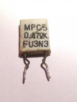
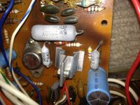
The image of 1 of the 4 resistors replaced with MO is attached. They were disintegrating. The other image is to illustrate the wire wound resistors I replaced. As stated earlier they had got very toasty. This is a common occurrence from what I can tell from other posts both here and on AK.
What would you recommend for a replacement of the CB701,751 protection devices. Don't like the sound of those🙁
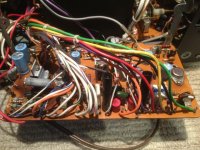
I also included a shot of the entire board for what it's worth. Lots of wires in the way, but will give an idea of the layout for discussion purposes.
Attachments
OK, thanks. I see you were talking about the replacement types. Those other wirewounds are only powdering in the ceramic dip coating. They will still last another few decades with or without the coating so don't fuss over them. It's cosmetic, not functional. The parts to be more concerned about are discoloured film caps and electrolytics which are the sign of ageing plastics and may be more critical if that affects the component.
I couldn't find thin emitter resistors of values above 0.22R on the bay. It will likely be necessary to use standard, square 3 or 5W WW resistors which, below an ohm resitance will be low inductance anyway. Dont use round types unless clearly described as low inductance types. You can buy these anywhere and you don't really need 5W resistors until you get around 100W amplifiers. Smaller will be better, I think.
The circuit breakers are a slow acting, once or twice only protection in disaster situations of accidental overdrive or dead shorted speaker leads etc. Now they would be replaced by output relays which even if a lot more expensive, double as DC protection and anti-thump delay. As far as being nasty things, they will not be much different to relays unless they are cycled a few times under adverse conditions causing arcing, erosion and poor contact. I imagine they have never been operated in earnest and are still pristine so don't be concerned if the audio is fine. Otherwise, fit relay protection with a kit and a good sized relay if your power supply has a suitable supply voltage to operate it.
Frankly, if I was happy with sound, I'd leave well enogh alone unless you plan to abuse it with heavy loads and high volume. Its not a big amp so I think it would have had an easy life to survive this long.
- Status
- Not open for further replies.
- Home
- Amplifiers
- Solid State
- Sony STR-7065 Distortion