i have a mds jb940 that i have been working on,i have cured all its issues but one still remains, one of the optical inputs dosent work on the jb940 it has on the back, 1 optical output,
the analogue in and out's 1 coaxial output, 1 coaxial input and two optical inputs, optical input no2 dosent work, cant understand why,
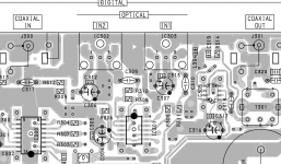
i have service manual and followed it back, on pin 1 it should have 3.3v it has about 0.25v, on that line there are only 2 caps before it is linked
to optical input no1 which works, i have replaced c306, no change, if i remember right the other is surface mount which is possibly beyond my
soldering capabilities, pin 2 is the ground pin which is seperated from pin 1 in circuit by the same caps, that circuit serves all the jacks and ends up at a transistor and switch, then pin 3 looks like a signal pin
that goes through some components to the ic, the other optical jacks go to the same ic.
anyway logic says if the power is not getting to no2 and its getting to no1 then it can either only be 1 of the 2 caps or somehow its not switching on.
there is a button on front panel that switches through all inputs, when it gets to no2 it says c71 no signal.
i know it sounds like a bit of a jumbled up story, but if anybody can give me a pointer it would be appreciated.
the analogue in and out's 1 coaxial output, 1 coaxial input and two optical inputs, optical input no2 dosent work, cant understand why,
i have service manual and followed it back, on pin 1 it should have 3.3v it has about 0.25v, on that line there are only 2 caps before it is linked
to optical input no1 which works, i have replaced c306, no change, if i remember right the other is surface mount which is possibly beyond my
soldering capabilities, pin 2 is the ground pin which is seperated from pin 1 in circuit by the same caps, that circuit serves all the jacks and ends up at a transistor and switch, then pin 3 looks like a signal pin
that goes through some components to the ic, the other optical jacks go to the same ic.
anyway logic says if the power is not getting to no2 and its getting to no1 then it can either only be 1 of the 2 caps or somehow its not switching on.
there is a button on front panel that switches through all inputs, when it gets to no2 it says c71 no signal.
i know it sounds like a bit of a jumbled up story, but if anybody can give me a pointer it would be appreciated.
Thanks for the reply, i do already have it, the thing is i dont understand part of the circuit, ie if its not one of those caps, one i have already replaced, thing is it maybe a switching fault, i dont understand how its switched or where the switching comes from
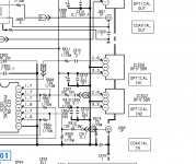
The source is IC1 (system control):
pin127 (selection between COAX and OPTICAL inputs)
pin126 (selection between OPT2 and OPT1 inputs)
The destination is IC300 (74HC153A switch):
pin2 (switching between COAX/OPTICAL)
pin15 (switching between OPT2/OPT1)
pin127 (selection between COAX and OPTICAL inputs)
pin126 (selection between OPT2 and OPT1 inputs)
The destination is IC300 (74HC153A switch):
pin2 (switching between COAX/OPTICAL)
pin15 (switching between OPT2/OPT1)
Last edited:
Have taken board out, i know i cant get an accurate reading with caps in situe, but being as most are surface mount i will be unable to remove them safely, so instead i looked for aything out of the ordenary, the multimeter has a fairly basic cap test, 4 settings only, there are 3 thru hole caps that are 100uf 10v, one tested at 79 the other 3 were between 119 and 123, the rest are surface mount, 2 are 1000p both are 1.025 on 2n setting the other 5 are 0.1, one is 131.7 another is 130.3 both on 100 uf setting the others were around 100 on 200n setting.
i also checked resistors, 1 is 75ohm and came out 73.8ohm, another 6 all 100ohm were tested between 99.5 and 100.5ohm and the last is 10kohm and came out at 10.29k ohms, did not see any cracked or dry joints while i was in there.
i also checked resistors, 1 is 75ohm and came out 73.8ohm, another 6 all 100ohm were tested between 99.5 and 100.5ohm and the last is 10kohm and came out at 10.29k ohms, did not see any cracked or dry joints while i was in there.
Begin by rechecking those voltages on the two receivers.
The ground and supply pins respectively are in parallel and so you have to be seeing correct voltages on pins 1 and 2 (3.3v and zero volts respectively). In post #1 you say:
So recheck that result and take it from there. Pin 1 of one receiver should be in direct electrical connection with pin 1 of the other. Same for the ground pin. Measure them with an ohmmeter.
The ground and supply pins respectively are in parallel and so you have to be seeing correct voltages on pins 1 and 2 (3.3v and zero volts respectively). In post #1 you say:
, on pin 1 it should have 3.3v it has about 0.25v,
So recheck that result and take it from there. Pin 1 of one receiver should be in direct electrical connection with pin 1 of the other. Same for the ground pin. Measure them with an ohmmeter.
Hi, i know that pins 2 are connected, i tested that with the continuity test, i am pretty sure, pins 1 are not, ive put the board back in now, but can do that with back cover off, so will get back to you when i have done that
I think ive done it fairly comprehensive
player off, in1 is the good input, continuity test.
A pin 2 of in1 to pin 2 of in2 - connection
B pin 1 of in1 to pin 1 of in2 - 1407
C pins 1 to 2 of in1 - 810
D pins 1 to 2 of in2 - 1075
power on, as above
A - connection audable
B - connection audable with a reading 1944
C 1.
D 1075
Voltage check, player on
in1 pins 2 to 1 - 3.35v
in2 pins 2 to 1 - 0.46v
in1 pins 2 to 3 - 3.03v
in2 pins 2 to 3 - 0.05v
i take it pin 1 is the one on the right
Pin 1 of IC302 should link to pin 1 of IC303... so if your 1407 is ohms then there is a break.
Pin 2 of IC302 (which is ground) should link to pin 2 of IC303.
Pin 3 of both IC302 and IC303 should according to the diagram be at around 2.8 volts DC as measured from ground.
Pin 1 is the one furthest from signal coupling caps C309 and C310.
You should be able to read the supply voltage across C312 and C313.
You should also use a scope and compare the signal on those caps when a known good source is connected to each input. Although you won't resolve the data you should see a 5 volts pk/pk signal that should leave no doubt it is OK.
Attachments
Hi have checked, the two caps with power applied, c313 checked out at 3.03v and c312 checked out at 0.25v, so the break could be further back, most of the components including ic300 is on the bottom of the board, i would say going further back i would unscrew board so as i can get at them.
i have player supported on either side plates with some books so could get the board floating so to speak, no scope i am afraid, mostly basic gear here.
i have player supported on either side plates with some books so could get the board floating so to speak, no scope i am afraid, mostly basic gear here.

the 0.25v is present on c306 also, could i bridge it and c307 instead of the 2 micro ones, i will need many pairs of specticles to do it to those two, i have a 12w iron, will have to try and find the pointed tip that came with it as its tip if small but for normal thru hole components, forgot to sat that there is no sign of any damage to pcb that i can see.
Last edited:
I have put a link between positive points of c306 and c307 and can report a successful outcome, i have tested from optical source (pc) and both inputs are now working as they should and switching as they should, many thanks for your advice, now ive got some work for this old girl to do, cheers
Excellent  I wonder if the fixture has taken a whack and cracked the print or something. Maybe an internal layer in the PCB if it is of that type.
I wonder if the fixture has taken a whack and cracked the print or something. Maybe an internal layer in the PCB if it is of that type.- Home
- Source & Line
- Digital Source
- Sony mds jb940