Single-Supply Preamps For Guitar
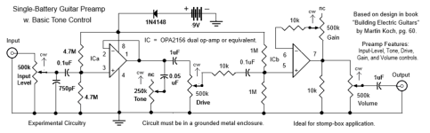
Here are six preamps for guitar using op-amps; each operated from a single 9V battery as the power supply, thus making them suitable for stomp-box applications. Sources for the diagrams are noted with the diagrams. The circuits are faithful to original diagrams but for minor changes, such as the adding of an input level control or the use of a pot in a negative feedback loop to provide the user with a gain control. However, while based on proven designs, these designs must still be considered experimental. Also, the diagrams originally posted had flaws, which were corrected according to advice from forum members here, who I thank for their help. The diagrams shown now are updated versions (but some may be updated again if needed).

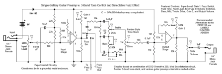
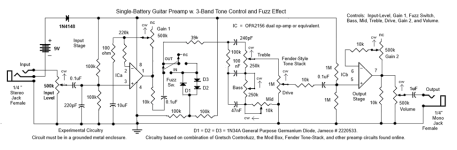
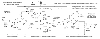
The specified IC is the OPA2156 dual low-noise op-amp IC, but an original TI unit can be expensive and may take a long time for delivery. So, I have listed a number of pin-compatible substitutes at the end of this post, all of which will provide good results.
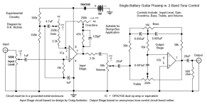
The next circuit features a Baxandall type of 2-band tone-control, followed by one with a Fender-style 2-band control, which works differently from the Baxandall-type, though both leave the mids fixed. For those who prefer three bands, all other circuits below involve 3-band Fender-style tone stacks.

Note the seemingly redundant Tone control at the output below. That is included to provide an additional means of shaping high-end response.

What follows next are the preamps with the 3-band tone-stacks having default Fender Bassman part-values.

Consider the difference in the way the input and output jacks are shown below. This would be a good way to do the foregoing circuits too, but I show this configuration only for the last two circuits. This one also has a fuzz circuit using diodes, providing clipping without having to overdrive op-amps. But if that is desired, an older dual JFET-input IC can be considered, having minimum supply voltage <= 4.5 V, such as the LF353.

The circuit below likewise has a diode-type fuzz circuit, but which is highly adjustable.


Here is the pinout diagram for a dual op-amp, along with pin-compatible example ICs.

ICs listed here should perform satisfactorily for the electric guitar and offer the least noise and distortion for circuits operated using a single 9V battery. They were chosen from among the best op-amps available today but whose minimum supply voltage is <= 4.5 VDC, since half of 9V is 4.5V, and a single-supply circuit sets the zero signal-reference operating-point midway between ground and the supply.
To get more distortion than the diodes provide, by overdriving a given circuit, use the LF353 instead of any of the ICs listed above. It is an older op-amp that will work with a single 9V battery as the supply and is a JFET-input op-amp, which means its overdriven tonality is preferred over that of most non-JFET-input op-amps. However, it will also work fine without being overdriven, and will not drain the battery nearly as fast as those listed above.
Note On Fuzz Circuits: The diode-based fuzz circuit used in the last two preamps are based on article “Build The Mod Box” by Thomas Henry and Jack Orman, in the May 1997 Electronics Now magazine (p.45). Obtain the article free online with this link.
https://www.muzique.com/news/images2/Mod_Box_May_1997.pdf
It originally specified the TL074 quad op-amp since it had four sub-circuits, and was operated from a split-supply. And despite being somewhat dated (25 years old), the circuitry has remained valid to this day, though I have adapted the diode arrays to conform to a single-supply circuit.
Additional Notes: Most circuits here are based on designs in the book “Building Electric Guitars” by Martin Koch. [$33.56 on eBay.] But the input stage of the second preamp is instead based on a design by Craig Anderton appearing in the Nov. 1981 issue of Guitar Player magazine. [Original issues start at $10.00 on eBay.] Those exact circuits cannot be found online, so a link to them is not available. Yet, I have depicted them accurately but for the minor additions I mentioned at the beginning of this post. Furthermore, while I receive much help diagnosing the diagrams I posted at first, I supplemented that help with online research, and an electronics textbook used at an accredited university. Consequently, all diagrams above have been updated and should be viable, but I would still treat them as experimental until after breadboard testing efforts have been completed.
Final Note: For comparison, the diagrams originally posted have been retained in the Attachments folder at the bottom of this post, while the updated versions are also there. I am embarrassed by the original ones, but proud of the new ones, though members who helped me with them deserve lots of credit. One thing should be mentioned, however, regarding the 0.2uF capacitors going to ground on the second stages of most of the diagrams. That, along with its associated resistor, sets the low-frequency cutoff for the associated op-amp at 80 Hz for 6-string guitar. But for bass-guitar, and 7-string or 8-string guitar, make it 0.43uF, for a 40 Hz cutoff. And for no low cutoff at all, it can be omitted. And by the way, the following replies correspond to the original diagrams, not the new ones. So, if you want to know what they are talking about, refer to the old diagrams as left in the Attachments.
EOF
Here are six preamps for guitar using op-amps; each operated from a single 9V battery as the power supply, thus making them suitable for stomp-box applications. Sources for the diagrams are noted with the diagrams. The circuits are faithful to original diagrams but for minor changes, such as the adding of an input level control or the use of a pot in a negative feedback loop to provide the user with a gain control. However, while based on proven designs, these designs must still be considered experimental. Also, the diagrams originally posted had flaws, which were corrected according to advice from forum members here, who I thank for their help. The diagrams shown now are updated versions (but some may be updated again if needed).
The specified IC is the OPA2156 dual low-noise op-amp IC, but an original TI unit can be expensive and may take a long time for delivery. So, I have listed a number of pin-compatible substitutes at the end of this post, all of which will provide good results.
The next circuit features a Baxandall type of 2-band tone-control, followed by one with a Fender-style 2-band control, which works differently from the Baxandall-type, though both leave the mids fixed. For those who prefer three bands, all other circuits below involve 3-band Fender-style tone stacks.
Note the seemingly redundant Tone control at the output below. That is included to provide an additional means of shaping high-end response.
What follows next are the preamps with the 3-band tone-stacks having default Fender Bassman part-values.
Consider the difference in the way the input and output jacks are shown below. This would be a good way to do the foregoing circuits too, but I show this configuration only for the last two circuits. This one also has a fuzz circuit using diodes, providing clipping without having to overdrive op-amps. But if that is desired, an older dual JFET-input IC can be considered, having minimum supply voltage <= 4.5 V, such as the LF353.
The circuit below likewise has a diode-type fuzz circuit, but which is highly adjustable.
Here is the pinout diagram for a dual op-amp, along with pin-compatible example ICs.
ICs listed here should perform satisfactorily for the electric guitar and offer the least noise and distortion for circuits operated using a single 9V battery. They were chosen from among the best op-amps available today but whose minimum supply voltage is <= 4.5 VDC, since half of 9V is 4.5V, and a single-supply circuit sets the zero signal-reference operating-point midway between ground and the supply.
To get more distortion than the diodes provide, by overdriving a given circuit, use the LF353 instead of any of the ICs listed above. It is an older op-amp that will work with a single 9V battery as the supply and is a JFET-input op-amp, which means its overdriven tonality is preferred over that of most non-JFET-input op-amps. However, it will also work fine without being overdriven, and will not drain the battery nearly as fast as those listed above.
Note On Fuzz Circuits: The diode-based fuzz circuit used in the last two preamps are based on article “Build The Mod Box” by Thomas Henry and Jack Orman, in the May 1997 Electronics Now magazine (p.45). Obtain the article free online with this link.
https://www.muzique.com/news/images2/Mod_Box_May_1997.pdf
It originally specified the TL074 quad op-amp since it had four sub-circuits, and was operated from a split-supply. And despite being somewhat dated (25 years old), the circuitry has remained valid to this day, though I have adapted the diode arrays to conform to a single-supply circuit.
Additional Notes: Most circuits here are based on designs in the book “Building Electric Guitars” by Martin Koch. [$33.56 on eBay.] But the input stage of the second preamp is instead based on a design by Craig Anderton appearing in the Nov. 1981 issue of Guitar Player magazine. [Original issues start at $10.00 on eBay.] Those exact circuits cannot be found online, so a link to them is not available. Yet, I have depicted them accurately but for the minor additions I mentioned at the beginning of this post. Furthermore, while I receive much help diagnosing the diagrams I posted at first, I supplemented that help with online research, and an electronics textbook used at an accredited university. Consequently, all diagrams above have been updated and should be viable, but I would still treat them as experimental until after breadboard testing efforts have been completed.
Final Note: For comparison, the diagrams originally posted have been retained in the Attachments folder at the bottom of this post, while the updated versions are also there. I am embarrassed by the original ones, but proud of the new ones, though members who helped me with them deserve lots of credit. One thing should be mentioned, however, regarding the 0.2uF capacitors going to ground on the second stages of most of the diagrams. That, along with its associated resistor, sets the low-frequency cutoff for the associated op-amp at 80 Hz for 6-string guitar. But for bass-guitar, and 7-string or 8-string guitar, make it 0.43uF, for a 40 Hz cutoff. And for no low cutoff at all, it can be omitted. And by the way, the following replies correspond to the original diagrams, not the new ones. So, if you want to know what they are talking about, refer to the old diagrams as left in the Attachments.
EOF
Attachments

Last edited:
The tone potmeter in the first schematic either does nothing at all or makes the first op-amp (IC1a) oscillate when set to a very low resistance. Is there a resistor missing between IC1a's output and the 0.05 uF capacitor?
Electric guitars are pretty high impedance at high audio frequencies, so the op-amps need to have a low equivalent input noise current. Op-amps with JFET or MOSFET inputs such as the OPA2156 meet that requirement, the LM4562 does not.
Electric guitars are pretty high impedance at high audio frequencies, so the op-amps need to have a low equivalent input noise current. Op-amps with JFET or MOSFET inputs such as the OPA2156 meet that requirement, the LM4562 does not.

MarcelvdG,
Good point about the tone-control. Perhaps a resistor could be placed between the tone-control's capacitor and the output of IC1a, but we could just as well rearrange the circuit to put the pot itself between said output and said capacitor. Additionally, adding a fixed resistor on the bottom of the pot would keep it from bottoming-out, which maximizes the effect of the capacitor. That you noticed this is well-taken. Alternatively, maybe the control should have been located between the 1uF coupling capacitor and the Drive control, or even between the input jack and the Input Level control, in which case it would work without adding a fixed resistor. At any rate, I have seen this series RC combination used as a tone-control in many guitar circuits.
As for the LM4562, I was looking at noise figures and whether it would work in a single 9V battery supplied circuit, but neglected the input impedance, assuming it was OK since this IC was listed among the 5 top dual op-amp ICs in an online search of the "best op-amps as of 2025". Yet, according to the spec-sheet, only its differential input impedance is low, around 30k (this is not a differential-input circuit), while its common mode input is very high, rated 1000M. Meanwhile, its input current noise is rated at only 1.6 pA/(sqrtHz), also impressive, while I listed its input voltage-noise rating in the table at the end of the post. That spec is quite respectable, and one of the reasons Texas Instruments touts this IC as offering "superior audio signal amplification for outstanding audio performance." So, I don't see why it would not work properly in the circuit under discussion.
Last edited:
When your guitar has an inductance of 4 H, the magnitude of its impedance increases from just above its DC resistance to about 500 kohm over the frequency range from 20 Hz to 20 kHz. At 6 kHz, roughly the frequency of the peak of the ITU-R 468 noise weighting curve, it's about 150 kohm. With a source impedance of 150 kohm, 1.6 pA/√Hz of equivalent input current noise has as much impact as 150 kohm • 1.6 pA/√Hz = 240 nV/√Hz of equivalent input voltage noise.
OK. But the highest note on a 24-fret guitar is an E at 1.32 kHz. The only signals from a guitar at 6 kHz would be harmonics above that highest note. Admittedly, that is only a bit over 2 octaves above the highest possible fundamental, but it would also be so weak as to make its noise figure practically inaudible, and therefore negligible, in my opinion. Yet, I could be wrong. If you can hear noise in higher-order overtones, more power to you. On the other hand, I do not contest your position. You are making valid points, and perhaps the inclusion of the LM4562 in my list should be reconsidered.
You could ask @bucks bunny . I understand noise optimization but know next to nothing about electric guitars, while the famous rabbit understands noise optimization, plays electric guitars and makes guitar electronics.
jan.didden,
I am not out to make money, or to claim something that is not my own. I give credit where it is due, but do claim "fair use" for posting diagrams for educational purposes. Yet, should someone complain, I will be happy to take down any post they object to. However, I would think that guys whose books and articles I reference would approve of the free promo.
I am not out to make money, or to claim something that is not my own. I give credit where it is due, but do claim "fair use" for posting diagrams for educational purposes. Yet, should someone complain, I will be happy to take down any post they object to. However, I would think that guys whose books and articles I reference would approve of the free promo.
Well I may be a bit sensitive. I have published books that still help me put bread on the table.
I really would hate to see them published wholesale like this.
Jan
I really would hate to see them published wholesale like this.
Jan
Several of those schematics have serious faults and shouldn't be built as is.
A redesign would constitute new IP.
A redesign would constitute new IP.
If faults are noticed, please be specific. Thanks.
By the way, I am not publishing anything "wholesale". Note that each diagram I show is made up of two stages, with each stage based on a different source schematic. Also, the circuits are based on those schematics, and are thus not exact copies, with many part-numbers and some wiring changed. That makes each of these diagrams my creation. And no-one can tell me that guitar-amp builders in the past and today have never used proven designs to come up with new ones. It's even a matter of public record. It is well known, for instance, that Jim Marshall based his early designs on a Fender Bassman. Did he ever pay Leo Fender any royalties for using that design?
Yet, mentioning a source amounts to free advertising. Who does not want free advertising for their offerings?
In the second op amp stage (in most of the schematics), the purported gain control does nothing.
Rayma,
Not according to the design equations for most op-amp circuits I have ever seen and have on hand. Gain depends on the amount of resistance in the negative feedback loop (and on the open-loop gain rating of the op-amp). If you make the resistance coming from the op-amp's output signal variable in that loop, the gain will be variable accordingly, where the amount of resistance is inversely proportional to the amount of gain the op-amp provides. This is why a unity-gain buffer has no resistor in the feedback loop (giving 100% feedback), while placing a resistor in the loop causes the op-amp to provide gain (by limiting the amount of negative feedback that is used). The only problem I have encountered with that is making the value of the variable resistor large enough to ensure that a change in its position actually produces a noticeable change in gain.
Not according to the design equations for most op-amp circuits I have ever seen and have on hand. Gain depends on the amount of resistance in the negative feedback loop (and on the open-loop gain rating of the op-amp). If you make the resistance coming from the op-amp's output signal variable in that loop, the gain will be variable accordingly, where the amount of resistance is inversely proportional to the amount of gain the op-amp provides. This is why a unity-gain buffer has no resistor in the feedback loop (giving 100% feedback), while placing a resistor in the loop causes the op-amp to provide gain (by limiting the amount of negative feedback that is used). The only problem I have encountered with that is making the value of the variable resistor large enough to ensure that a change in its position actually produces a noticeable change in gain.
Misstatement in my previous reply. My fault.
The amount of resistance in a feedback loop is directly proportional to the amount of gain the op-amp provides, not inversely proportional.
However, while I am able to post this correction, for some reason I am suddenly not allowed to edit the previous post, instead of posting this correction.
Readers should note this correction.
The value of a resistance in the feedback loop of an op-amp is proportional to the amount of gain the op-amp provides, up to its rated limit, called its "open-loop gain", meaning no feedback loop at all (i.e., infinite resistance between the op-amp's output and its inverting input).
Funny thing. I was just able to edit this reply. And I was able to edit my previous replies until just about fifteen minutes ago.
I conclude that some kind of timer has been placed on my reply capabilities that was not there before I posted my last reply.
Last edited:
Did anyone check the minimum operating voltage of these opamps. For example, the 4562 will work for +-2.5v so it will work with a 9v battery.
In the case of an ideal op-amp, ideal resistor and ideal connections, it is easy to calculate from first principles that rayma is correct.
This is the amplifier configuration rayma referred to. In the full schematics, RFB is the series connection of a fixed and a variable resistor.

There is by definition zero voltage between the input pins of an ideal op-amp, so the input voltage Vin that is applied to the positive input also occurs on the negative input. The input current of an ideal op-amp is also zero by definition, so there is a current of 0 A flowing through RFB. Assuming an ideal resistor that exactly follows Ohm's law, there will be zero voltage drop across it. As a result, the output voltage also equals Vin. It's therefore a voltage follower no matter what value RFB has.
With a real op-amp and everything else also real, using a large RFB may cause enough negative phase shift with the op-amp input capacitance and wiring capacitances to cause oscillations. Oscillations would cause big signals in the megahertz range, excessive distortion and quite possibly a gain reduction. Then again, with some package and wiring capacitance from output to negative input, the phase shift may never get negative enough to cause oscillations. It's quite unpredictable. On top of that, you get thermal noise from RFB.
It would be a whole different story if besides the feedback resistor, there were a resistor or an RC series network from the negative input to ground.
This is the amplifier configuration rayma referred to. In the full schematics, RFB is the series connection of a fixed and a variable resistor.
There is by definition zero voltage between the input pins of an ideal op-amp, so the input voltage Vin that is applied to the positive input also occurs on the negative input. The input current of an ideal op-amp is also zero by definition, so there is a current of 0 A flowing through RFB. Assuming an ideal resistor that exactly follows Ohm's law, there will be zero voltage drop across it. As a result, the output voltage also equals Vin. It's therefore a voltage follower no matter what value RFB has.
With a real op-amp and everything else also real, using a large RFB may cause enough negative phase shift with the op-amp input capacitance and wiring capacitances to cause oscillations. Oscillations would cause big signals in the megahertz range, excessive distortion and quite possibly a gain reduction. Then again, with some package and wiring capacitance from output to negative input, the phase shift may never get negative enough to cause oscillations. It's quite unpredictable. On top of that, you get thermal noise from RFB.
It would be a whole different story if besides the feedback resistor, there were a resistor or an RC series network from the negative input to ground.
So, if I had put the Tone control in my first preamp of post #1 on the output of IC1b instead of IC1a, that's a different story?
I actually agree that a capacitor between the 10k resistor at the output and ground would help with circuit performance.
However, we are not dealing with an "ideal" op-amp, but a real one.
Even so, the main mistake I made was that there should indeed be a resistor from the inverting input of IC1b to ground. Then the ratio of that resistor's value over the total resistance in the feedback loop would properly set the gain, as usual for a non-inverting gain stage. However, the original circuit (in Koch's book) on which that of IC1b is based does not have such a resistor (though it uses a fixed 1M resistor in the feedback loop instead of a combination of potentiometer and fixed resistor), while the circuit configuration is otherwise much the same. [See: Building Electric Guitars by Martin Koch, English version, originally self-published in Germany, 2nd Ed. 2001, pg. 61.] So, should we assume that Koch got it wrong too?
No. And though I agree the project needs tweaking, I believe you guys are out to find fault with me, for some reason, and are just piling on. My suspicions were raised yesterday when I was suddenly unable to edit my post #14 after re-reading it and noticing a typo that needed correcting but was therefore forced to post a correction in post #15, though I had been posting and editing my posts previously many times that same day -- up to that point.
Be aware that I am not just a member here but a doner as well. I have donated money to this cause. And while I once before removed myself from this forum, I only recently returned to give it a second chance. I would therefore appreciate Moderators adjusting the settings on my account such that I am able to edit both my past and present posts, as was usual before post #14. I have sent an email to that effect via the Contacts page but have yet to receive a response.
In any case, not one to leave unfinished business undone, I shall be updating my diagrams and posting the updated versions as soon as I have time.
The editing period in this forum is set to 30 minutes. The time between your post #14 and post #15 was almost an hour.
The best way to contact a mod is via the Report button at the lower left side of the post window.
Very nice of you to give the forum another chance!
BTW, nobody is 'out to find fault with you'; it's about the circuits!
From the thread it is clear that you have limited understanding of these circuits.
That's no shame, we've all been there, and nobody is blaming you.
But it does make us careful about adopting these circuits without critical review.
People like Marcel van de Gevel who take the time and effort to point out issues and explain things should be thanked, not waved (woven?) off with some waffling.
Jan
Last edited:
Agreed. And I will be changing my diagrams in an effort to take everyone's advice. Thanks.
Question: How is it that all of my editing options were changed, not just timing out with a post that took too long?
Note: To accuse me of having "limited understanding" of electronic circuits is an insult. If I have made mistakes, OK. I will stand corrected when they are pointed out to me. But since I based circuits in question on proven designs, I must myself be viewing advice given here with some "critical review".
Last edited:
- Home
- Design & Build
- Electronic Design
- Some Single-Battery Guitar Preamps