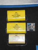
6uf, rated 115vac at 400Hz. It needs to be big. They look like either a mixed dielectric or a film type construction. If you calculate the reactance at 400Hz you will see how much "current" can flow at 400Hz. If they are specced for aircraft then reliability will be paramount. 500Vac. Think what the pk/pk voltage is.
OK, thanks. I was planning to experiment with these, use them as bypass caps for a tube circuit DC power supply but I'm not sure if that's OK.
No question they are OK for that usage as long as you keep voltage ratings in mind. 115vac rating suggests a cap of at least 200vdc working... but they don't explicitly say so I would err on the side of safety and say multiply the ac rating by 1.414 and then knock 20 % off that figure. They are probably rated way over those figures but as they don't say... play safe.
Thanks again, well, I was planning to use the 115V caps in a 150VDC circuit. If it blows up I will have to do a lot of cleaning so.....I guess not.
To put some real figures vs experience into the equation...
UK mains, historically 240 vac which is 340 volts pk. Mains filter caps in older TV's were often 400vdc rated... and they went bang. 1000vdc rated caps were I think 630vac rated and never failed. So on that basis 630 vac being "equivalent" to a 1000vdc cap means your 115 cap should be good to go. Even better, yours are 400Hz rated... tougher job than 50/60Hz
UK mains, historically 240 vac which is 340 volts pk. Mains filter caps in older TV's were often 400vdc rated... and they went bang. 1000vdc rated caps were I think 630vac rated and never failed. So on that basis 630 vac being "equivalent" to a 1000vdc cap means your 115 cap should be good to go. Even better, yours are 400Hz rated... tougher job than 50/60Hz
Last edited:
Agree.
Not forgetting that being specified for such a life threatening use if wrong , they are probably way overbuilt.
As in: a dead cap in a TV or amplifier may mean a boring evening ... but a dead one in a plane may mean a very exciting one ... the wrong way 🙁
Not forgetting that being specified for such a life threatening use if wrong , they are probably way overbuilt.
As in: a dead cap in a TV or amplifier may mean a boring evening ... but a dead one in a plane may mean a very exciting one ... the wrong way 🙁
Mooly, it's not the first time you help me out. You're a very good person. In fact you make me feel embarrassed of my (sometimes) devious ways.To put some real figures vs experience into the equation...
UK mains, historically 240 vac which is 340 volts pk. Mains filter caps in older TV's were often 400vdc rated... and they went bang. 1000vdc rated caps were I think 630vac rated and never failed. So on that basis 630 vac being "equivalent" to a 1000vdc cap means your 115 cap should be good to go. Even better, yours are 400Hz rated... tougher job than 50/60Hz
* JMFahey - you would be surprised by the fact that sometimes there are bogus parts on planes.
Big for the value and voltage means good dielectric.
In unknown cases like this I measure "d" with rlc meter and 0,000 means mkp, styroflex or teflon.
In unknown cases like this I measure "d" with rlc meter and 0,000 means mkp, styroflex or teflon.
I would give them an audio test before putting them in a signal path except if they are going into a speaker cross over where the currant rating is what you are looking for.
They look like power factor correction parts from cabin lighting and may do a few funny things in a signal path as opposed to a power path.
I class a cross over to be a power path.
The Test.
Add a resistor in series with the capacitor to be tested equal to the input impedance of your amplifier and ground the other end of the capacitor.
Add a coupling capacitor to the input of your amplifier.
A microphone or other high sensitivity input is best and apply 30 volts to the resistor.
Tap on it with a pencil rubber or your finger nail and you will hear if it is microphonic.
If this produces sound only use them for decoupling.
Repeat the test with audio types before accepting them when buying.
There are quite a few duffers out there.
- Status
- Not open for further replies.
- Home
- Design & Build
- Parts
- Some questions about aircraft caps.