Let's take a look at some early Power Amps. You probably know that the first transistor radio was the Regency TR1 from 1955. Delco made the first transistor car radio in 1956.
But in HiFi, tubes ruled. Designers were trying to figure out how to best use transistors in audio, but the germanium devices of the day were fragile, and amplifier architectures were evolving. Here is a look back at some early work that shows the evolution.
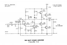
Here's one from 1959 GE Transistor Manual using germanium PNPs:
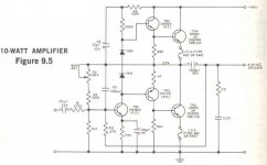
Here's a similar one from the 1962 GE Transistor Manual:
Silicon transistors were produced from 1958, and by 1965 were taking over. Here is a design using mostly silicon transistors, with a lone germanium PNP.
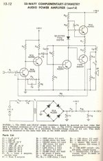
The above amp has fewer parts but better performance, partly because of bootstrapping the VAS. It still uses one germanium PNP, which had better performance than silicon PNPs of the day. I built this as part of the Heathkit AR-14. Sounded great at the time, but so-so today.
This 70 watt amp from 1967 shows what engineers could do with excellent silicon power transistors:
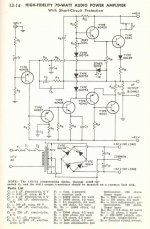
Noteworthy is the output protection, absence of an output capacitor and adjustments for offset and bias current. I built this as part of the Heathkit AR-15. It sounded OK, and I appreciated the protection circuit many times.
One of my favorite designs from the same era (1967) is the JBL T Circuit Amp.
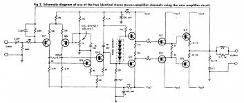
This has a long-tailed pair input, and complementary NPN and PNP outputs. Note the use of three different supplies for the pre-driver, driver and output transistors, due to the restricted Vce of the output transistors. This T configuration is the reason for the name. Note too that the VAS uses another long-tailed pair, following opamp philosophy. I have one of these, and while it's not up to today's standard, it was revolutionary at the time.
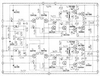
In this era, late 60s to mid 70s, Japanese companies built better and better amps and receivers, for less cost. Nearly all American makers folded except the high end. Here is an example of an amp from a popular Japanese receiver from 1972, the Pioneer SX 828. Note the similarity of the amp to the JBL T Circuit.
Hope you enjoyed that look back at some early designs.
But in HiFi, tubes ruled. Designers were trying to figure out how to best use transistors in audio, but the germanium devices of the day were fragile, and amplifier architectures were evolving. Here is a look back at some early work that shows the evolution.
Here's one from 1959 GE Transistor Manual using germanium PNPs:

Here's a similar one from the 1962 GE Transistor Manual:

Silicon transistors were produced from 1958, and by 1965 were taking over. Here is a design using mostly silicon transistors, with a lone germanium PNP.

The above amp has fewer parts but better performance, partly because of bootstrapping the VAS. It still uses one germanium PNP, which had better performance than silicon PNPs of the day. I built this as part of the Heathkit AR-14. Sounded great at the time, but so-so today.
This 70 watt amp from 1967 shows what engineers could do with excellent silicon power transistors:

Noteworthy is the output protection, absence of an output capacitor and adjustments for offset and bias current. I built this as part of the Heathkit AR-15. It sounded OK, and I appreciated the protection circuit many times.
One of my favorite designs from the same era (1967) is the JBL T Circuit Amp.

This has a long-tailed pair input, and complementary NPN and PNP outputs. Note the use of three different supplies for the pre-driver, driver and output transistors, due to the restricted Vce of the output transistors. This T configuration is the reason for the name. Note too that the VAS uses another long-tailed pair, following opamp philosophy. I have one of these, and while it's not up to today's standard, it was revolutionary at the time.
In this era, late 60s to mid 70s, Japanese companies built better and better amps and receivers, for less cost. Nearly all American makers folded except the high end. Here is an example of an amp from a popular Japanese receiver from 1972, the Pioneer SX 828. Note the similarity of the amp to the JBL T Circuit.

Hope you enjoyed that look back at some early designs.
Thanks for sharing.
Interesting how the 'T' circuit (from Bart Locanthi [sp?] who was the chief engineer at JBL IIRC) with the driver base stoppers has remained as probably the best solution for class AB solid state amps.
I remember looking at some of these circuits in the RCA manual when I was quite young in the late 60's, very early 70's. There was a circuit diagram convention, especially in the US, of drawing circuits with the V- to the top of the circuit like your first image that was quite confusing if you were not used to it. This also brings back good memories of paging through the Amateur Radio Handbook with designs for transmitters and receivers. All good stuff!
🙂
- Status
- Not open for further replies.