I have four 1626s hanging around and I need a new project. I don't have any need for a preamp, so it appears my only option is a Darling amp.
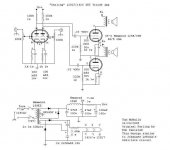
My power requirements are not very high since I listen quietly in a small apartment. But, is it worth the effort to go with a double Darling? Is it further worth the effort to DC couple the two stages? I am thinking the following for the 'usual' Darling (see attached schematic)...
Seems my best bet (for the money) is to source transformers from Edcor. Thinking XPWR177 for power (200-0-200 at 70mA) into a pi filter using their 15H, 347-ohm choke - should be good for 245V or so. Output transformers will be GXSE10-8-5k or GXSE15-8-5k.
This amp will run full-range, so good bass performance is a must. To that end, would it be worthwhile buying the GXSE15 instead of the GXSE10?
Also, it looks to me (and LTSpice) that most people run the 1626s in their Darlings above the stated maximum plate dissipation of 5W. Why is that exactly? Are there any adverse effects? Would hate to burn these tubes up since they are becoming rare.
I am just looking for some last minute tips before I order parts. My budget is tight, so I cannot afford to make many mistakes.
Thanks all!
Hi,
Double or single tube really depends on your speakers actually. What speakers do you plan to use?
DC coupling will not have the capacitor or interstage transformer to further color the sound, but it comes with its' cons as well. Since there are plenty of good capacitors and interstages around, I would not mind going for RC or IT coupling.
The differences in size of the output transformer you mention will not matter much. If you look for full bass bandwidth, then the primary inductance of the output transformer will decide how low / much bass you have. If GXSE15 has more primary inductance than GXSE10, then go ahead with the 15.
Do not run it higher than the rated plate dissipation or you will risk burning out the tube earlier than it is designed for. 🙂
Ken

Think the best is to go with an original amp from Bob Danielak himself.
I´ve made a darling some years ago to the schematic of Jeremy Epstein:
Jeremy Epstein's "Darling" SE 1626 Amps
This is a parallel 1626 with powerfull 1,6Watts🙂
Sound is very well as with all darlings and no hum or hiss or anything.
I don´t know the Edcors but generally more iron is more(better) bass.
Good luck,
Hilmar
Are there any ST shaped driver tubes that would pair well with the 1626? I was thinking about trying the 6N7G, but I have not found much data about this tube.
Are there any ST shaped driver tubes that would pair well with the 1626?
I use 6J5's, but they are a little low in gain but sound quite good.
Thomas Mayer is a strong proponent of the 6N7 tube and has lots of information about them on his blog, including single ended amp designs.
VinylSavor: Tube of the Month: The 6N7
VinylSavor: Tube of the Month: The 6N7
Thank you for the link; a nice write-up there.
He states that the sections of the 6N7 must be run in parallel in order to use this tube as a class A driver, but I don't see why this is so. If it is a question of plate resistance, it looks to me that the 6N7 plate resistance is half that of a 6SL7 at similar currents.
Admittedly, I am not terribly knowledgeable with tubes. But, couldn't one use a single 6N7 to drive both channels of a Darling (as the 1626 are reportedly easy to drive) as long as the cathode bypass cap is large enough to minimize crosstalk?
The sections have to be run in parallel on the 6N7 because there is only 1 common cathode for the two triode sections. So, they cannot be used as independent channels for stereo.
The common cathode shouldn't be a problem if the cathode resistor is bypassed with a big capacitor. The tube could then handle two channels of audio.
Wondering if someone can clear up a simulation issue for me...
The schematic in post #2 is essentially a 'typical' Darling, being run at Bob Danielak's original operating point. But is this too hot? I'd hate to go to all the trouble of building this, only to burn up my 1626s.
I've put the circuit into LTSpice and it behaves oddly. For some reason, the 1626 grid sits at +13V above ground. Plate has ~245V on it, cathode sits ~34V above ground for 34mA bias. Frequency response and sine waves look normal, though. What is going on here?
No takers? I suspect something is amiss with the model.
But,that notwithstanding, it still looks to me that the 'normal' Darling operating point is too hot... Schematics show ~250V on the plate at 25-27mA. That is way over the 5W plate limit.
Should the cathode resistor be 1.5k or so instead of 1k?
But,that notwithstanding, it still looks to me that the 'normal' Darling operating point is too hot... Schematics show ~250V on the plate at 25-27mA. That is way over the 5W plate limit.
Should the cathode resistor be 1.5k or so instead of 1k?
I can't speak to your Spice simulations but a lot of Darling type amps run the 1626 tube a little above 5 watts.
Mine uses the DIYTUBE "Clementine" board and it runs about 5.2 watts. The tube seems plenty capable of running above the 5 watt book specification.
Mine uses the DIYTUBE "Clementine" board and it runs about 5.2 watts. The tube seems plenty capable of running above the 5 watt book specification.
So, no reliability issues from running above the spec? The 1626 tube is getting harder to come by...
I mean, it looks to me that the original Darling runs the plate at 250V * 27mA = 6.75W. Way high!
When tubes were cheap many were run above the recommended value but it will shorten tube life. E.g. I've got a design that runs the EL84/6BQ5 at 280 V @ 58mA. Guitar amps often run tubes above their ratings but tubelife is notoriously short. If you want long life then run them at 70%- 80% of the maximum rating, they'll last almost indefinitely. One other design I've got is running the EL84/6BQ5 at 200V and 50mA which has a reputation of running almost forever without changing the output tube. Output at that level is approx. 3.5 Watt (not taking in account OPT losses).
nelson Pass mentioned that the first watt is the most important one. Most people hardly can determine a 2dB difference in output however distortion gets noticed rather quickly. Hence the triode - it has very smooth clipping while being tolerant of changes in speaker impedance. UL clips almost like solid state and is tolerant of changes in speaker load. Pentodes clips somewhere between unfortunately is intolerant of changing speaker loads. Take your poison.
nelson Pass mentioned that the first watt is the most important one. Most people hardly can determine a 2dB difference in output however distortion gets noticed rather quickly. Hence the triode - it has very smooth clipping while being tolerant of changes in speaker impedance. UL clips almost like solid state and is tolerant of changes in speaker load. Pentodes clips somewhere between unfortunately is intolerant of changing speaker loads. Take your poison.
Last edited:
What is the best way to fix the bias point without affecting the characteristic sound?
The schematic posted by Garbage seems to have a good operating point, but I am not planning to DC couple.
The schematic posted by Garbage seems to have a good operating point, but I am not planning to DC couple.
In class A it makes not much difference to use either a cathode resistor or to use adjustable negative voltage because the anode current does not change markedly.
There are purists who are of the opinion that negative voltage is the best way, certainly with pentodes there is some (minor?) audible difference.
What I've done in the past with my 6L6-GC amplifier is to have a fixed resistor with a 12.5 watt rheostat parallel. The values were chosen so that if the rheostat would develop an open situation that the tube would not fail plus that I could do tube rolling (KT66, KT77, KT88 and EL34 with James 6123HS OPT, adjust the primary) and adjust the anode current with the rheostat.
Personally I would keep it simple and go to the tube specifications and select the anode current at the voltage and then read off the graphs the negative voltage required. Then calculate the cathode resistor by dividing the negative voltage and the anode current. The anode voltage across the tube needs to be measured between cathode and anode. Hope this helps.
PS
In pentodes the sound is more affected by the height of the anode voltage, e.g. at higher voltage the 6L6-GC and the EL84 have more 3rd harmonics in comparison to 2nd harmonics than at a lower voltage. Have not checked this but suspect the same applies to triodes.
What I am trying to convey is that at the same voltage there should not be a noticeable difference in sound quality when you change the current.
- Status
- Not open for further replies.
- Home
- Amplifiers
- Tubes / Valves
- Some 1626 Darling Amp Questions