Hello all! I think most of us are running loudspeaker DC protection in our DIY amplifiers; even if they can be considered highly reliable such protection also alleviates power on/off thump. I'm also noticing quite a few threads on the use of solid-state technology in this application and it appears to be unanimously better than mechanical relays when properly implemented. What I'm wondering is whether there is enough interest in a loudspeaker protection board/module to ultimately create a run of PCBs/assembled modules. Here are some of the specifications I'd expect to achieve:
I have some rough ideas about parts and how this can be implemented, and will doubtless build at least one prototyped unit for my own use. I will present schematics and code here along the way and perhaps with enough interest the design could be refined and developed into a PCB/module for distribution.
So let me know what you think! I will update this thread with my own independent designs regardless, but hopefully this could become a project for the community 🙂
- Suitable for amplifiers with up to +/-80V power rails
- Fast detection by use a microcontroller, around 50mS for DC down to 1V, potential for very fast detection of DC above 90% of supply voltage
- Latching off when faults occur until fault is removed
- Stereo module, independent channel detection could be a feature if desired
- Compact SMT design
- Modest cost, hopefully below £15 per stereo module (depends on PCB run size)
- Fast loss of AC detection and on/off muting delays
- Could be built requiring just the amplifier secondary AC supply, efficient rectification and down-regulation on board, easy to retro-fit module
I have some rough ideas about parts and how this can be implemented, and will doubtless build at least one prototyped unit for my own use. I will present schematics and code here along the way and perhaps with enough interest the design could be refined and developed into a PCB/module for distribution.
So let me know what you think! I will update this thread with my own independent designs regardless, but hopefully this could become a project for the community 🙂
You might consider having the solid state relays turning off the supply rails when protection in invoked rather than having them in series with the amplifier's output.
This is discussed here:
http://www.diyaudio.com/forums/solid-state/235841-michael-kiwanukas-soa-paper.html
This is discussed here:
http://www.diyaudio.com/forums/solid-state/235841-michael-kiwanukas-soa-paper.html
Last edited:
For good microcontroler use we can add:
1- On / StandBy controle, so the microprocessor is on with an auxiliary PSU;
2- Turn on inruch current control;
For protection:
1- I suposse the arrangent used in last Marantz projects is more interesting as it act decopling speaker from amplifer fastly;
2- We also must check temperature from heatsink to protect power devices;
3- I personally prefer high quality mechanical power relays;
Please show us your ideas and code.
Regards from Brazil
We have indeed not long had a series of MOSFET DC protection circuit threads. Most were simple and small enough for any form of construction, and still fully effective as relay replacements. There is a long thread here opened by Bonsai that kicked this series off (for soon obvious reasons).
http://www.diyaudio.com/forums/solid-state/191449-output-relays.html Several proposals are discussed there. Also, fleshed-out in this rather good paper on his website.
http://hifisonix.com/solid-state-loudspeaker-relay/ (click on the highlighted link below the page's text)
Another couple of designs by prominent members are also kicking around and a search brings up a number of related threads.
There's nothing like more variety and different ideas but SMT probably isn't the way to go for most DIYs. Not only do we fumble and lose SMD parts because we can't set up our workplace properly, but I think that though many are quite keen to try out this form of relay, they will probably also want to use existing thru-hole stocks for a project like this.
Last edited:
I'd be very interested in this. I was planning on designing something similar, but using Rod Elliot's protection circuit instead of a microcontroller.
I would prefer if the bulk of it was designed around through hole components, but would be in a for a few PCB's either way.
I would prefer if the bulk of it was designed around through hole components, but would be in a for a few PCB's either way.
I got in touch with Mr. Elliot and he wrote me that his code was not fast enough for his microcontroller version.
I suppose the best code for this application must use microprocessor high priority interruption to be reliable and fast.
Another thing. Using microcontroler we can also mute amplifier input and realise output relay(or MOSFET Switch) first and then realise amplifier input as it is done in commercail quality amplifier.
I aggred with PTH project. But if we apply all points, the project become big and complex to DIYer.
Last edited:
michaelkiwanuka: I looked at your paper and it does indeed look like very complete and elegant protection. To also achieve power on/off muting though I think the loudspeaker disconnect is the only workable solution?
r_merola: Standby control and a trigger output for mains switching/inrush limit control switching could be added and I think would be valuable. As you identified, this does require an external PSU (6VA will almost certainly be sufficient however). I am less concerned by temperature monitoring, a correctly specified heatsink shall keep the output devices safe except perhaps where unacceptably low impedance loads are driven?
Ian Finch: The main motivation for SMT is the wider availability of suitable MOSFETs in this package type (D2PAK), as well as the lower cost of these parts. Nothing would be below SOIC size however as I know below this it gets tricky to hand-solder. Certainly through-hole designs will be presented as the system will be developed with these parts, it's only if the system gets to the point where there is enough interest to make up PCBs that surface mount will be considered since total costs could drop to around half! I'd probably solder the main IC, the PIC, anyhow since it'll need to be programmed over ICSP.
Stormrider: Yep, my original concept here was for an integrated solid-state version of the type of protection offered by Rod.
WRT code speed, the code would certainly use interrupts and timers so running speed should be no issue. The intended scheme shall detect 'zero' crossings (actually signals about +/-1V to trigger) and look for a negative going crossing following a positive crossing; failure to see one within 50mS (or perhaps selectably less for mid/treble amps?) it shall assume DC offset of greater than 1V and hence a fault condition. Care must be taken however to ensure it correctly handles asymmetric signals. ADC may be involved, I assume this would be the slowest code element however most can take several ksps so it shouldn't be an issue.
Additional input muting would be nice but as you say, it begins to break the realms of an add-on module as it requires connection to many points within the amplifier. It is hard to design a universal board of this type as there are so many different conditions it can be used under, so it is perhaps best to limit functionality to the most essential ones in the interests of cost?
Thanks for all your input so far!
Member
Joined 2009
Paid Member
I built a MOSFET solid state relay with dc detection circuit, basic circuit only and I also found that SMD was the best option - there are many choices of good components for SMD but not so much through-hole. In particular, the optovoltaic driver I used was only available in SMD and MOSFET choice was clearly best with SMD too.
I think there is more fear of SMD than the reality of it. SMD has a huge range of part sizes, you can choose to work with relatively large parts and you can also mix and match with through-hole. I ended up using SMD - less holes to drill too.
I think there is more fear of SMD than the reality of it. SMD has a huge range of part sizes, you can choose to work with relatively large parts and you can also mix and match with through-hole. I ended up using SMD - less holes to drill too.
Last edited:
Hi,
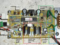
i already did some worked on how to protect the speakers using a microprocessor same as your are proposing. My design do the following functions.
1 Turn ON/OFF the amplifier by ramp the AC at zero crossing- this will prevent the inrush current
2 Mute the amplifier in case of a LM3886
3 Delay the speakers outputs until the PS voltage settle
4 close/open SSR if high current it is detected
5 monitoring the heat sink temp and shutdown if it too high
Also display the temp, current usage and the watts used.
I can provide some technical know how if you want.
Attached it is a picture of my board. The board it is been working for 5 months in an LM3886 amplifier with no problems.
Attachments
Yeah nice idea 🙂
I've read & looked @ both Bonsai & michaelkiwanuka papers which are Very interesting.
Ideally i think that possibly more than one version "might" be required. Say, one for up to a few 100W & another for 1000W plus !
The SMD parts could just be restricted to the power Mosfets ?
I've read & looked @ both Bonsai & michaelkiwanuka papers which are Very interesting.
Ideally i think that possibly more than one version "might" be required. Say, one for up to a few 100W & another for 1000W plus !
The SMD parts could just be restricted to the power Mosfets ?
Bigun: Yep, its the range of parts at lower cost than their through-hole counterparts and reduced PCB costs (no/few holes) that makes SMT attractive for this. Here's the photovoltaic isolator and MOSFETs I've found which should do an excellent job at modest cost:
Panasonic APV1121S Photovoltaic isolator
PSMN8R7-80BS MOSFET
tauro0221: That looks very well thought-out! I guess current detection is by a hall-effect sensor such as:
ACS712ELCTR-20A-T
A nice solution, do you try to detect AC and DC currents differently and prioritise disconnect of DC? This should be quite effective however it does require the user to tailer the current detection threshold based on the amplifier they are using.
I am still undecided on exactly the best way to detect DC quickly and reliably. My original plan was to split detection between an integrated/low-pass and unfiltered signal, when a rise in the integrated signal is seen the micro would look for a zero cross on the unfiltered signal, if one is not seen after 25mS (half cycle at 10Hz is 50mS, 90 degree phase shift of 1st order LPF already delayed sensed signal of 10Hz by 25mS) then the disconnect shall operate. I think this could work? It's just getting the bipolar signals into the PIC with the fewest components. Let me know if you know any faster/more efficient scheme!
I use a 2pole filter.
20k+3u3F, then 51k+1uF
Reacts quickly to high DC offset and slows to ~½second when DC offset ~+-1.5V
20k+3u3F, then 51k+1uF
Reacts quickly to high DC offset and slows to ~½second when DC offset ~+-1.5V
As much as I've looked at alternative DC detection, by waiting for zero crossings, digital filtering with PIC18F or detecting multiple consecutive similar samples above a threshold, none seem to be as operationally rugged as the simple low-pass filter and clipper arrangement so commonly seen. The digital filtering should reduce parts count slightly but doesn't seem worth it for the large amount of additional software complexity?
However, the PIC does facilitate latching the output off until the fault is removed, simple power on delay sequence and fast loss of AC detection. We could use a PIC comparator input from the DC detector and allow the user to set up the protection sensitivity based on their amplifier output power, as Zero D mentioned earlier. This could help in the scenario that small delicate speakers are used with maybe a 10W amplifier, but a disconnect with DC fault only occurs within 50mS if the offset is 70V! If the system takes in an AC feed from the amplifiers supply line then it can do this automatically by rectifying and scaling the voltage and meaauring it by the ADC.
However, the PIC does facilitate latching the output off until the fault is removed, simple power on delay sequence and fast loss of AC detection. We could use a PIC comparator input from the DC detector and allow the user to set up the protection sensitivity based on their amplifier output power, as Zero D mentioned earlier. This could help in the scenario that small delicate speakers are used with maybe a 10W amplifier, but a disconnect with DC fault only occurs within 50mS if the offset is 70V! If the system takes in an AC feed from the amplifiers supply line then it can do this automatically by rectifying and scaling the voltage and meaauring it by the ADC.
Hi,
In my first designed I used the speaker voltage level to open or close the SSR for the speakers. Then I found the ACS712 hall effect current sensor and switched to it. Now I am looking at the speaker output current and when reach the trigger level I open the SSR to the speaker. It is take micro seconds to detect a high current. With the micro you can close and open the speaker SSR depending of the setting you set in the program. It is a simple sensor and it can read -/+ current. The ranges are 5,20,30,50 and 100 amps.
Also it eliminated some components.
I like the idea of using a SS Relay and have considered it. The only thing that has held me back is not knowing if its working or not since you don't get the 'click' of the standard electro/mechanical relay.
Member
Joined 2009
Paid Member
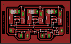
I used a simple low pass filter envelope detector for the dc. The details are here: http://www.diyaudio.com/forums/soli...simple-symmetric-amplifier-7.html#post2936405
and the pcb I made is shown in the attachment.
The MOSFETs I used were from Digikey: IPB200N15N3G
The opto-voltaic I used was: TLP190B - it needs an external resistor for fast turn-off
It's for 3 channels. I used a red/green LED to indicate the status of the circuit - whether the 'relay' is closed or open
The trouble is, I didn't incorporate a turn-on delay and this is something that I realize as being necessary for it to be really useful.
Attachments
Last edited:
If you look at the control and protection circuit section of my e-Amp it might help stir up your creative juices. The ucontroller response time is indeed a problem, so the trick is to get the protection circuit to drive the MOSFET relay directly. If you size things right, you can get them to switch in 10's of microseconds. The job of the MCU is then to latch them off and monitor the amplifier output to see if the fault remains or if its been cleared by disconnecting the speakers. In the e-Amp protection board, DC offset, short circuit, over temp and speaker muting plus in rush current control are taken care of. Code was written in Keil C and is about 1 k when compiled for NXP 89LPC922 (8051 core).
Anyway, good luck wit your project!
🙂
Anyway, good luck wit your project!
🙂
Member
Joined 2009
Paid Member
Bonsai - is a kit available or was this a one-off ? (the web shop on your website doesn't work in my browser)
No, I need to remove this tab - sort about that.
However,
I will put the Gerbers up this weekend. I am just too busy to run a web shop.
Andrew
However,
I will put the Gerbers up this weekend. I am just too busy to run a web shop.
Andrew
- Status
- Not open for further replies.
- Home
- Amplifiers
- Solid State
- Solid state speaker protection system - interest check