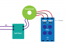
I've got a classic inrush-current-blowing-fuses problem with my DIY power supply. Here's the setup (see layout attached):
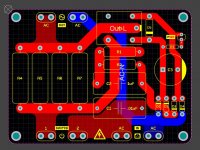
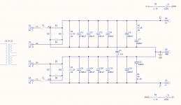
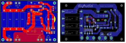
1. I've got AC mains coming into my soft start PCB (based on the DIYaudio design here, and this deisgn thread).
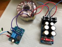
2. From the soft start, we go to a 400VA, 22-0-22 transformer.
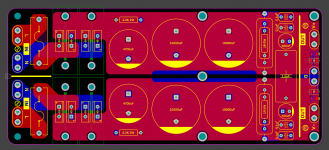
3. Finally we go to the power supply, with post-secondary fuses and a DC output of +/-28V (hopefully!).
I started by using 3A fuses (slow blow), and found that they blow instantly, as soon as the mains is connected to the soft start. I tried a couple of fuses up to 7A, with the same result. In each case, the fuses blow immediately, and the power LEDS on the PSU board light up and slowly dim as the capacitors discharge.
I also tried lowering the value of C2 on the soft-start PCB from 1uF to .22uF, to increase the soft-start delay, but the same thing happens.
The LED on the soft-start board slowly powers up and down when the mains is connected and disconnected. I do hear the click of the relay after the interval chosen by C2, so the relay appears to be working. Regardless, given that the fuses on the PSU blow immediately it would be safe to assume the soft-start isn't doing its job.
Either the problem is with my soft-start or the PSU. I suspect the soft-start board is at fault, given that the PSU is a fairly simple unregulated design.
Can anyone help me out here? 🙂
1. I've got AC mains coming into my soft start PCB (based on the DIYaudio design here, and this deisgn thread).
2. From the soft start, we go to a 400VA, 22-0-22 transformer.
3. Finally we go to the power supply, with post-secondary fuses and a DC output of +/-28V (hopefully!).
I started by using 3A fuses (slow blow), and found that they blow instantly, as soon as the mains is connected to the soft start. I tried a couple of fuses up to 7A, with the same result. In each case, the fuses blow immediately, and the power LEDS on the PSU board light up and slowly dim as the capacitors discharge.
I also tried lowering the value of C2 on the soft-start PCB from 1uF to .22uF, to increase the soft-start delay, but the same thing happens.
The LED on the soft-start board slowly powers up and down when the mains is connected and disconnected. I do hear the click of the relay after the interval chosen by C2, so the relay appears to be working. Regardless, given that the fuses on the PSU blow immediately it would be safe to assume the soft-start isn't doing its job.
Either the problem is with my soft-start or the PSU. I suspect the soft-start board is at fault, given that the PSU is a fairly simple unregulated design.
Can anyone help me out here? 🙂
Attachments

Last edited:
If you power the 'soft start' board without the 400vA transformer and the fuse of any value blows, the 'soft start' board is faulty/incorrectly assembled.
If you power the 'soft start' board without the 400vA transformer and the fuse of any value blows, the 'soft start' board is faulty/incorrectly assembled.
Thanks JonSnell. The soft-start board isn't fused, and I definitely wouldn't connect the PSU directly to the soft-start (and thus directly to mains, without a transformer), so I'm not sure what you're referring to?
Do you first check the operation of your soft start?
Start by checking if with the transformer connected to the soft start you get the secondary voltages of the transformer and if it is good, your power supply card is in doubt.
Start by checking if with the transformer connected to the soft start you get the secondary voltages of the transformer and if it is good, your power supply card is in doubt.
Maybe you are using a 120V primary transformer on 240V mains.
Not kiddingf, I have seen that.
Or you have a shorted turn in it.
Try just the transformer alone. primary to mains through a 100 to 150W incandescent bulb.
I suggest a quartz lamp "stick" there, since screw on home type incandescent bulbs are hard to find nowadays.
If lamp blinks and then stays orange or red, transformer is fine.
If it lights almost 100% bright and stays there, transformer is faulty or mis rated.
I would disconnect the transformer and get the soft start working right first.
You can see how long the relay takes to switch.
You could even put a mains lamp on output to see delay depending on delay time.
I hate relays so made my own soft start using a triac and an 8 pin microcontroller.
Works a treat. If I connect a mains lamp to it I can see the lamp getting brighter on power up.
Fantastic suggestions, thanks everyone! Will tick them off one-by-one as soon as I'm back in the workshop.
Are your rectifying diodes isolated from the heatsinks on the power supply board?
I would add another diode, that should rectify the problem ! TIC
Are your rectifying diodes isolated from the heatsinks on the power supply board?
Yup! Silpads on each, and no continuity tested on the multi-meter.
Sorry to insist but also insulating gun so that the screw does not make contact between the diodes?
Just wondering, is the pcb debugged so it works? C3 is very big because you use this cap as capacity voltage division. I have only 47 uF. High value => lower voltage across the relay coil. How did you calculate the C3 value?
sorry abza
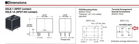
I think there is an error in the layout regarding the relays....it's possible?
Oh dear, I think that may be it (as embarrassing as that would be!) I see the datasheet of the G5LE lists the land pattern as the "bottom view", which could have been the culprit. Let me check with a multimeter and report back! Thanks!
And one more addition about several parallel 180 R resistors - I think overall resistance have to be larger. I think, it have to be about 100-200 Ohm equivalent, so if there are four resistors - their nominal have to be about 400-600-800 Ohm.
With 180 Ohm nominal (45 Ohm equivalent) - we can have up to 4-5 peak primary current (220 VAC), so it can be about 40-50 secondary peak current (for 220V/22V transformer).
I think we have to keep peak primary current in 1-2 Amperes range. (It means primary current limiting resistance of 220-100 Ohm for 220 VAC). Sertainly, it depends of nominal power of our device too.
Last edited:
For some weird reason relays are seen from the bottom. Quite useless if you use a pcb cad.from datasheet
😕I do not understand ..... where should they show the pins in the DS?For some weird reason relays are seen from the bottom. Quite useless if you use a pcb cad.
- Status
- Not open for further replies.
- Home
- Amplifiers
- Power Supplies
- Soft Start circuit not working?