Here is how I do it.
Show in the pic attached is a basic diagram of a typical test set up.
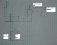
The amplifier under test is connected to a 4-ohm dummy load and the output monitored on an oscilloscope and an AC voltmeter. The amplifiers audio input is terminated/shorted to ground.
The earth return for the power supply is broken with a series 4 ohm power resistor / dummy load, which is driven by another audio power amplifier connected to a signal generator.
This allows a large audio frequency (and beyond) signal to be superimposed onto the power supply rails.
The same method can be used to measure the PSRR of each rail individually, but then independent floating supplies have to be provided for the positive and negative rail voltages.
Show in the pic attached is a basic diagram of a typical test set up.
The amplifier under test is connected to a 4-ohm dummy load and the output monitored on an oscilloscope and an AC voltmeter. The amplifiers audio input is terminated/shorted to ground.
The earth return for the power supply is broken with a series 4 ohm power resistor / dummy load, which is driven by another audio power amplifier connected to a signal generator.
This allows a large audio frequency (and beyond) signal to be superimposed onto the power supply rails.
The same method can be used to measure the PSRR of each rail individually, but then independent floating supplies have to be provided for the positive and negative rail voltages.
Attachments
G.Kleinschmidt said:Here is how I do it.
Show in the pic attached is a basic diagram of a typical test set up.
Ok, now I get it. Very good.
The problem I have is that the readings on a voltmeter or scope aren't as "tactile" as the method I used, where I could actually listen to for the "ripple". I guess I could use a speaker instead of the scope or meter?
Don't forget that the supply voltage becomes the sum of the AC voltage plus the DC component. I'd suggest using a small signal injection, say .1 to 1V, perhaps 5V max.
Also, one could inject white noise and look at the output on a spectrum analyzer.
Small power resistors say .1 to 1 ohm could be put in series with the supply caps and the signal injected there to do the single ended test as shown in the attached diagram. The cap then acts as both the supply filter cap and the signal coupling cap:
http://baselaudiolabs.googlepages.com/psrr_PLB.JPG
Pete B.
PB2 said:Don't forget that the supply voltage becomes the sum of the AC voltage plus the DC component. I'd suggest using a small signal injection, say .1 to 1V, perhaps 5V max.
Also, one could inject white noise and look at the output on a spectrum analyzer.
Small power resistors say .1 to 1 ohm could be put in series with the supply caps and the signal injected there to do the single ended test as shown in the attached diagram. The cap then acts as both the supply filter cap and the signal coupling cap:
http://baselaudiolabs.googlepages.com/psrr_PLB.JPG
Pete B.
Hi Pete.
Problem with a signal of only 0.1 - 1V is that you'd need a higher test frequency before you'd be able to pull anything out of the noise at the output.
By driving the ground of the power supply the total supply voltage stays fixed, just the relation to ground changes.
Most amps should be able to take at least a +/-10% variation here with ease (and should be designed to, to account for variations in mains voltage).
Cheers,
Glen
andy_c said:Hi Glen,
Would this work without the 4 Ohm resistor (the horizontal one)?
Hi Andy.
I just put the resistor there because my test amplifier is happier driving a load.
Cheers,
Glen
The same basic setup will work for simulator PSSR test.
Glen,
are there any special things you recommend for SPICE setup?
I use now like 0.1 Vrms for preamplifiers and 1Vrms for poweramps.
100 Hz. Because of 50Hz full bridge gives 100 Hertz ripple.
Glen,
are there any special things you recommend for SPICE setup?
I use now like 0.1 Vrms for preamplifiers and 1Vrms for poweramps.
100 Hz. Because of 50Hz full bridge gives 100 Hertz ripple.
By line up..The same basic setup will work for simulator PSSR test.
An externally hosted image should be here but it was not working when we last tested it.
3 voltage sources.. [SINE(60 2 120)],[SINE(60 2 500)]-for US..,and a pulse at 2V(HF harmonics) .. all fed to .1R resistors.. gives a realistic
representation of real world conditions..do the same for
negetive rail.🙂
OS
G.Kleinschmidt said:
Hi Pete.
Problem with a signal of only 0.1 - 1V is that you'd need a higher test frequency before you'd be able to pull anything out of the noise at the output.
By driving the ground of the power supply the total supply voltage stays fixed, just the relation to ground changes.
Most amps should be able to take at least a +/-10% variation here with ease (and should be designed to, to account for variations in mains voltage).
Cheers,
Glen
Hi Glen,
It's it true that the rail to rail voltage is the same, but each rail is the DC + AC value, and since the load is referenced to ground the AC component changes the SOA of the output devices in the event that testing is done with an input signal. I'm fairly sure you realized this but just wanted to point it out for others.
I agree with your 10% value as a guide line but people should also think about it case by case. One could drop the DC a bit with a Variac to simulate supply droop then add in the PSU ripple.
Pete B.
lineup said:The same basic setup will work for simulator PSSR test.
Sure, but why would you want to do it that way in SPICE?
For PSRR evaluation in SPICE you use AC analysis and get your f Vs dB graph straight up.
PB2 said:
Hi Glen,
It's it true that the rail to rail voltage is the same, but each rail is the DC + AC value, and since the load is referenced to ground the AC component changes the SOA of the output devices in the event that testing is done with an input signal. I'm fairly sure you realized this but just wanted to point it out for others.
You're confusing me Pete!
The load is referenced to ground, but so is the input. The idea here is to only measure at the output that which originates from the power supply leads.
Cheers,
Glen
G.Kleinschmidt said:
Sure, but why would you want to do it that way in SPICE?
For PSRR evaluation in SPICE you use AC analysis and get your f Vs dB graph straight up.
Hi Glen,
Can you explain this? I'd like to know how to do this. I've searched for "measuring PSRR in Multisim" but found nothing.

roender said:
It is enough PSRR for your taste?
Hi roender,
-70db? I think so, but look at the difference the addition of an RC does between the frontend and back, sharing the same dirty supply:

Aqua trace with the RC.
roender said:What are the values of R and C?
Please plot the PSRR graph until 1Mhz 🙂
I have changed the pic in post #14 to show the inclusion of the RC plotted to 10MHz.
R value is 4.7ohm, C value is 220uF.


- Status
- Not open for further replies.
- Home
- Amplifiers
- Solid State
- So how do you measure power amplifier PSRR then?